EasyManuals Logo

Mercury 75 Service Manual

Mercury 75
574 pages
To Next Page IconTo Next Page
To Previous Page IconTo Previous Page
Page #138 background imageLoading...
Page #138 background image
2D-18 - ELECTRICAL 90-830234R3 DECEMBER 1997
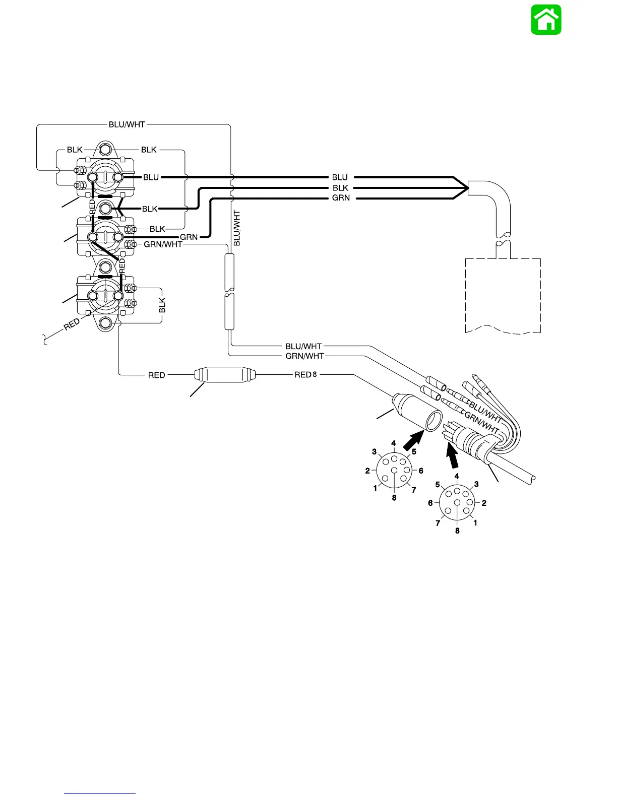
Power Trim System Wiring Diagram (3 Cylinder Models Using COMMANDER
2000 Side Mount Remote Control)
23886
b
c
d
e
f
g
h
a
BLK = BLACK
BLU = BLUE
BRN = BROWN
GRY = GRAY
GRN = GREEN
PUR = PURPLE
RED = RED
TAN = TAN
VIO = VIOLET
WHT = WHITE
YEL = YELLOW
a - Power Trim Pump Motor
b - Trim Solenoid “UP”
c - Trim Solenoid “DOWN”
d - Engine Starter Motor Solenoid
e - Red (+) Battery Cable
f - Fuse Holder (20 Amp Fuse)
g - Engine Wiring Harness Connector
h - Remote Control Wiring Harness Connector

Table of Contents

Other manuals for Mercury 75

Questions and Answers:

Question and Answer IconNeed help?

Do you have a question about the Mercury 75 and is the answer not in the manual?

Mercury 75 Specifications

General IconGeneral
Horsepower75 hp
StartingElectric
Cylinders3
Warranty3 years
Shaft Length20 in. or 25 in.

Related product manuals