2A-20 - ELECTRICAL 90-830234R3 DECEMBER 1997
Capacitor Charging #1 CDM
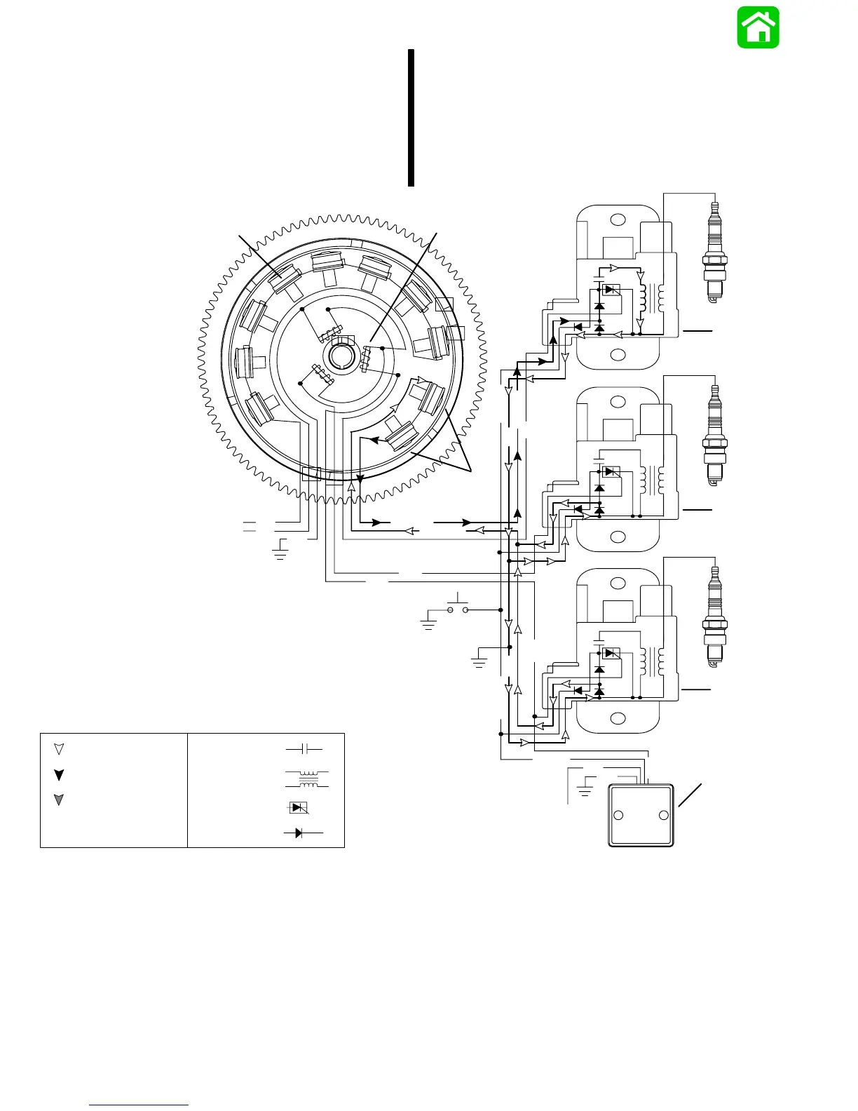
The STATOR assembly is mounted to the block
below the flywheel and has 3 CAPACITOR CHARG-
ING COILS wound in series. The FLYWHEEL is fitted
with 6 permanent magnets inside the outer rim. The
flywheel rotates the permanent magnets past the
capacitor charging coils causing the coils to produce
AC voltage (260-320 volts). The AC voltage is then
conducted to the CAPACITOR DISCHARGE MOD-
ULES (CDM), where it is rectified (DC) and stored in
a capacitor. The stator voltage return path is through
the ground wire of the other CDM and back through
that CDM’s charging coil wire to the capacitor
charging coils.
N
BLK
N
S
S
S
S
S
S
N
N
N
N
N
S
GRN/WHT
WHT/GRN
YEL
YEL
BRN
BLK
WHT
+
+
+
_
_
_
WHT/GRN
PPL
BRN
BLK
BLK/YEL
BRN
BLK/YEL
BLK
BLK/YEL
2
3
PPL
a
b
c
d
e
f
g
h
i
j
1
Return Voltage
CAPACITOR-
Source Voltage
COIL-
SCR-
DIODE-
Trigger Voltage
a - Battery Charging Coils
b - Trigger Coils
c - Capacitor Charge Coils
d - CDM #1
e - CDM #2
f - CDM #3
g - Rev. Limiter (Not Used On All Models)
h - To Ignition Switch
i - Stop Switch
j - To Voltage Regulator

 Loading...


