2B-22 - ELECTRICAL 90-830234R3 DECEMBER 1997
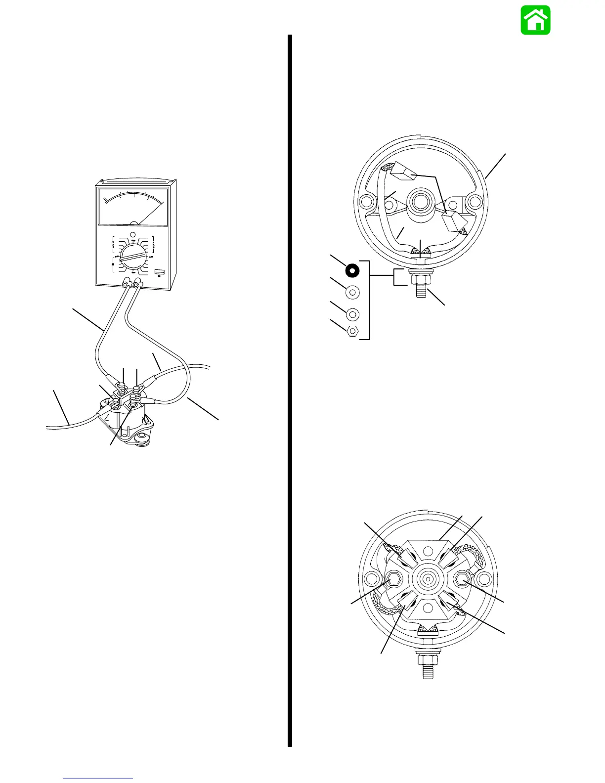
STARTER SOLENOID TEST
1. Disconnect all wires from solenoid.
2. Use an ohmmeter (R x 1 scale) and connect me-
ter leads between solenoid terminals 1 and 2.
3. Connect a 12-volt power supply between sole-
noid terminals 3 and 4. Solenoid should click and
meter should read 0 ohms (full continuity).
4. If meter does not read 0 ohms (full continuity), re-
place solenoid.
a
a
b
1
3
4
2
b
51809
a - 12-Volt Supply
b - VOA Leads
Brush Replacement
STARTER REASSEMBLY
1. If brushes were removed, replace as follows:
a. Install POSITIVE brushes (along with POS-
ITIVE terminal) into commutator end cap.
c
i
b
a
h
d
d
e
f
g
11660
a - End Cap
b - POSITIVE Brushes
c - POSITIVE Terminal
d - Insulating Bushing
e - Washer
f - Split Washer
g - Hex Nut
h - Long Brush Lead
i - Push Lead into Slot
b. Install NEGATIVE brushes (along with brush
holder).
c
b
d
a
b
d
a
11656
a - POSITIVE (+) Brushes
b - NEGATIVE (–) Brushes
c - Brush Holder
d - Bolts (Fasten NEGATIVE Brushes and Holder)

 Loading...


