5B-34 - MID-SECTION 90-830234R3 DECEMBER 1997
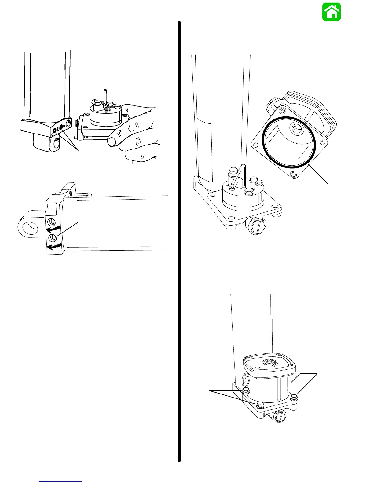
2. Install O-rings on cylinder and secure manifold
assembly to cylinder using screws. Torque
screws to 100 lb. in. (11.3 N·m).
a
28381
a - O-ring (2)
a
53962
a - Screws [100 lb. in. (11.5 N·m)]
3. Secure power trim unit in soft jawed vise.
Reservoir Installation
1. Inspect O-ring on bottom of reservoir for cuts or
abrasions. Replace as required.
a
53960
a - O-ring
2. With O-ring aligned in groove in bottom of reser-
voir, install reservoir on manifold.
3. Secure reservoir to manifold with 4 bolts and
washers. Torque bolts to 70 lb. in. (8.0 N·m).
a
a
53959
a - Bolts and Washers [Torque to 70 lb. in. (7.9 N·m)]

 Loading...


