5B-38 - MID-SECTION 90-830234R3 DECEMBER 1997
Purging Power Trim Unit
Manual release valve must be in full closed position
during power trim purging and operation.
1. Secure power trim unit in soft jawed vise.
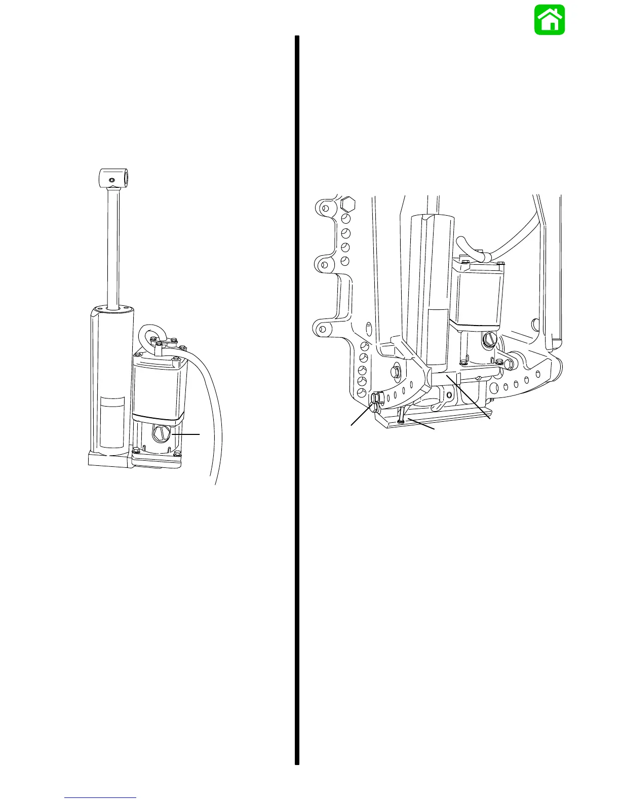
2. Remove fill cap. Add Quicksilver Power Trim and
Steering Fluid (92-90100A12) or Automatic
Transmission Fluid (ATF) Type F, FA or Dexron III
up to threads of reservoir. Install cap.
a
53964
a - Fill Cap
3. Using a 12 volt power supply connect POSITIVE
lead to GREEN wire, NEGATIVE lead to BLUE
wire and drive trim rod to the DOWN position.
Connect POSITIVE lead to BLUE wire and NEG-
ATIVE lead to GREEN wire and drive trim rod to
the UP position. Recheck fluid level, add fluid as
required and repeat cycle until fluid level remains
at lower portion of threads.
Power Trim Unit Installation
1. Apply 2-4-C w/Teflon (92-825407A12) to lower
pivot pin bore and pivot pin surface.
2. Position trim cylinder assembly (BOTTOM
FIRST) between clamp brackets and route trim
pump electrical harness through access hole in
starboard clamp bracket.
3. Start lower pivot pin into pivot pin bore and posi-
tion lower cross pin (RETAINED) in its respective
hole.
a
b
c
53965
a - Trim Cylinder Assembly
b - Lower Pivot Pin
c - Lower Cross Pin

 Loading...


