2A-14 - ELECTRICAL 90-830234R3 DECEMBER 1997
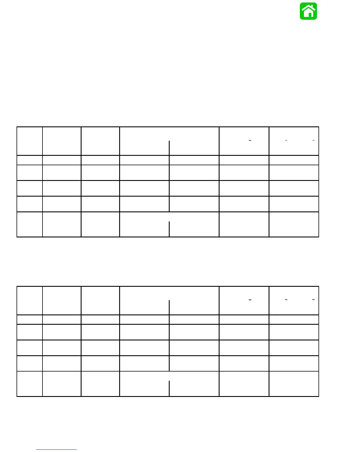
Ignition System DVA Specifications Test Chart
IMPORTANT: BEFORE attempting the ignition system checks, following, read the preceding pages of
these instructions to become familiar with the proper test sequence and procedures (particularly any
“Safety Warnings” and “Cautions”). ALL tests are performed with lead wires connected – terminals
exposed. SWITCH BOX MUST BE GROUNDED (CASE TO ENGINE BLOCK) FOR ALL TESTS – IF NOT,
SWITCH BOXES MAY BE DAMAGED.
3 Cylinder Stators
75 Manual with 9 Ampere Stator 398-9873A20, USA-0D283222 thru 0G227199
75/90 Electric with 16 Ampere Stator 398-9710A3, USA-0D283222 thru 0G280043
Belgium-09793577 thru 09879064
ADI
DVA Leads
Voltage
Readin
(1)
Voltage Reading
Test
Seq. Test
Selector Sw.
Position
Red Black
@ 300-1000
RPM
@ 1000-4000
RPM
1-A Coil Primary 400 VDC* Coil (+) Terminal Coil (–) Terminal 150-250 180-280
2-A
Sw. Box –
Stop Circuit
400 VDC*
Black/Yellow (3)
Sw. Box Terminal
Ground 200-360 200-360
3-A
4-A
Stator –
Low Speed
400 VDC*
Blue Sw.
Box Terminal
Ground 200-300 200-330
3-A
4-A
Stator –
High Speed
400 VDC*
Red Sw.
Box Terminal
Ground 20-90 130-300
[See Note (1)]
5-A
.
–
Bias
40 VDC
Ground
White/Black
Sw. Box Terminal
2-10 10-30
4 Cylinder with 16 Ampere Stator 398-9710A31
USA-0D283222 thru 0G301750
Belgium-09793577 thru 09885527
ADI
DVA Leads
Voltage
Readin
(1)
Voltage Reading
Test
Seq. Test
Selector Sw.
Position
Red Black
@ 300-1000
RPM
@ 1000-4000
RPM
1-A Coil Primary 400 VDC* Coil (+) Terminal Coil (–) Terminal 150-250 180-280
2-A
Sw. Box –
Stop Circuit
400 VDC*
Black/Yellow (3)
Sw. Box Terminal
Ground 200-360 200-360
3-A
4-A
Stator –
Low Speed
400 VDC*
Blue Sw.
Box Terminal
Ground 200-300 190-310
3-A
4-A
Stator –
High Speed
400 VDC*
Red Sw.
Box Terminal
Ground 20-90 140-310
[See Note (1)]
5-A
.
–
Bias
40 VDC
Ground
White/Black
Sw. Box Terminal
2-10 10-30
(1) Using meter only, REVERSE LEAD POLARITY; connect leads as specified.
* If using a meter with a built-in DVA, place selector switch in the DVA/400 VDC position.

 Loading...


