90-830234R3 DECEMBER 1997 ELECTRICAL - 2B-11
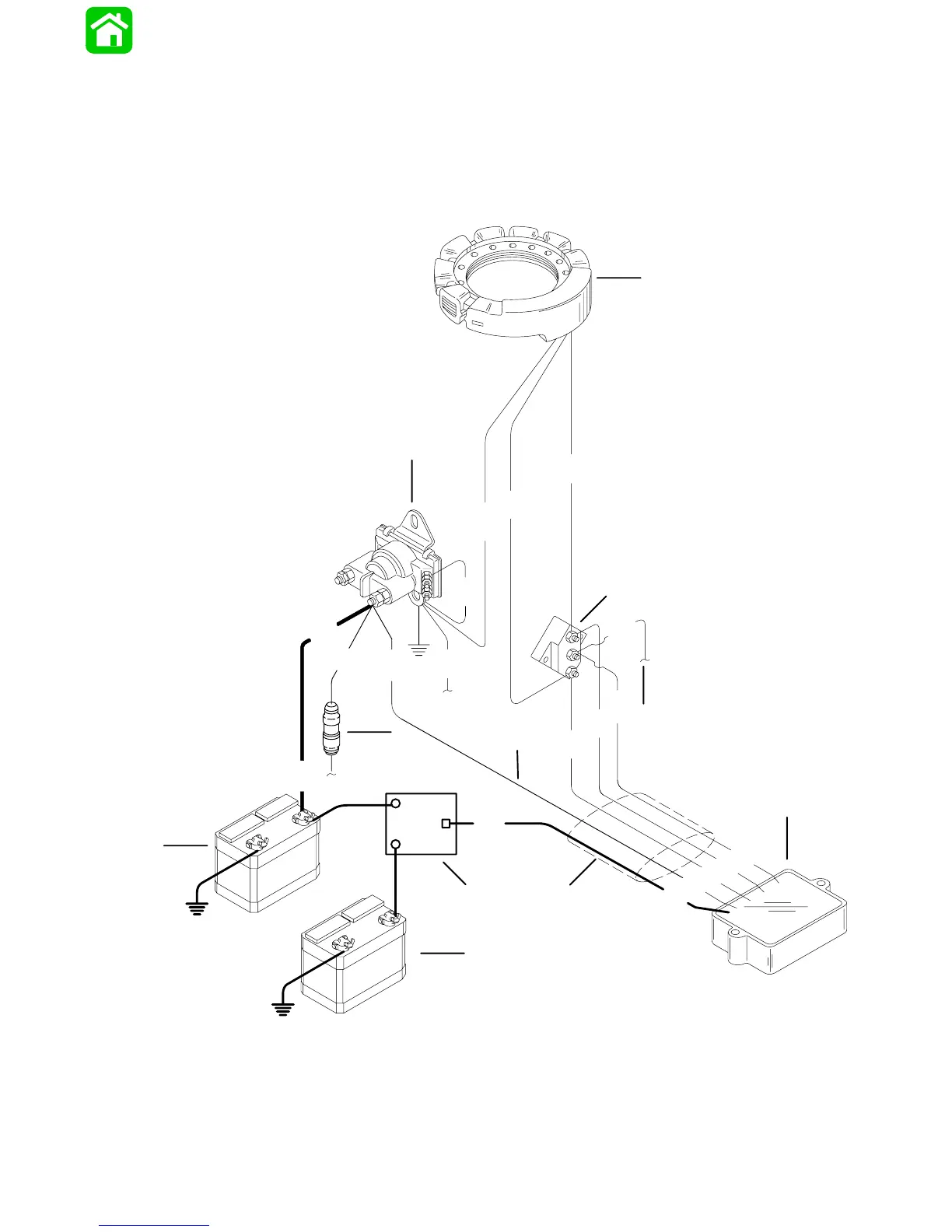
3 Cylinder Battery Charging Diagram
(with BLACK STATOR) with Battery
Isolator
IMPORTANT: After electrical connections are
made, coat all terminal connections using Quick-
silver Liquid Neoprene (92-25711), to avoid cor-
rosion.
51051
BLK
GRY
RED
RED
RED
RED
B1
B2
RED
A
BLK
YEL
YEL
BLK
YEL
YEL
GRY
GRY
YEL
YEL
RED
RED
a
j
b
c
d
e
f
g
i
h
k
l
BLK = BLACK
BLU = BLUE
BRN = BROWN
GRY = GRAY
GRN = GREEN
PUR = PURPLE
RED = RED
TAN = TAN
VIO = VIOLET
WHT = WHITE
YEL = YELLOW
a - Stator
b - Terminal Block
c - To Tachometer
d - Voltage Regulator/Rectifier
e - Battery Isolator
f - Auxiliary Battery
g - Start Battery
h - To Remote Control Harness
i - 20 Ampere Fuse
j - Starter Solenoid
k - Small Red (Sense)Lead
l - Large Red (Output) Lead

 Loading...


