5B-16 - MID-SECTION 90-830234R3 DECEMBER 1997
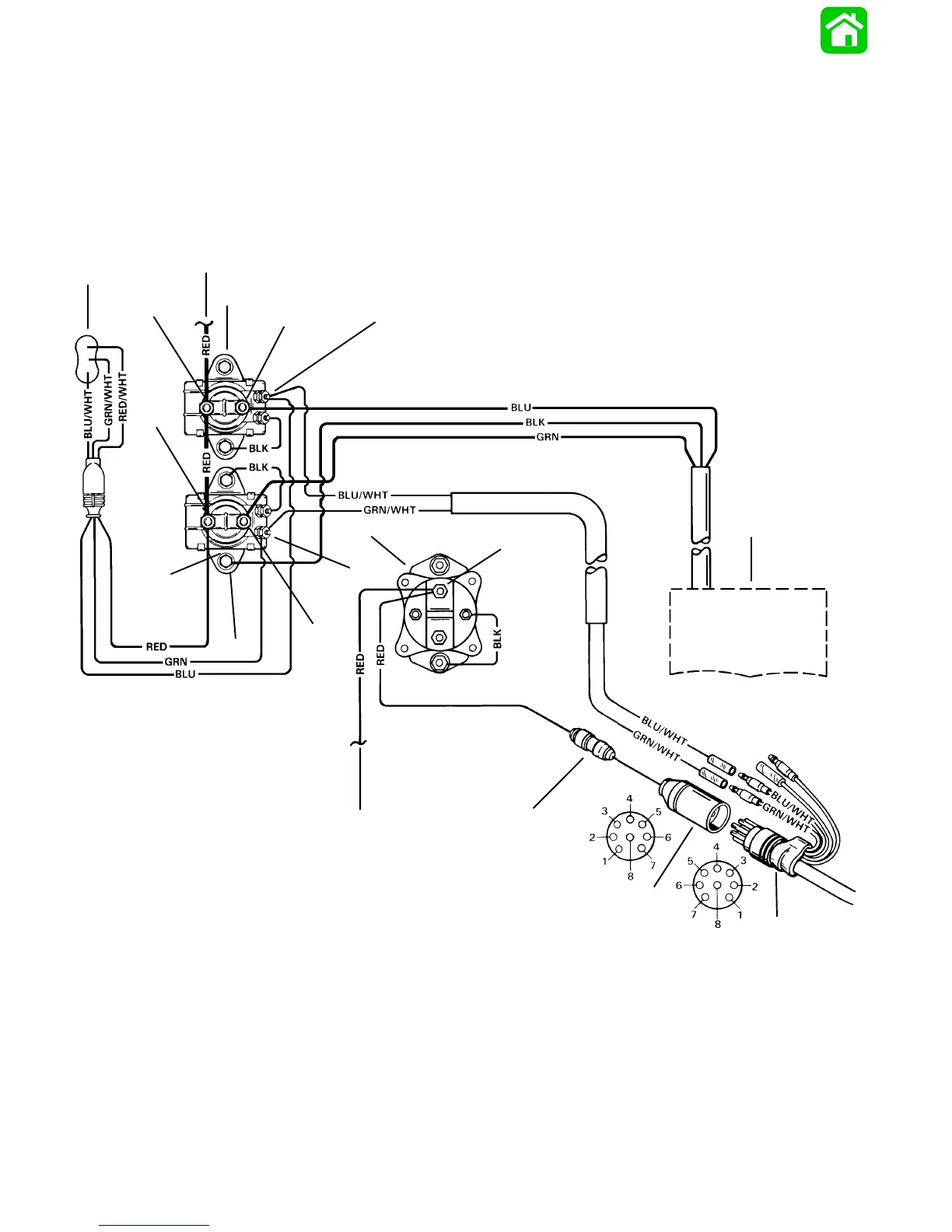
Power Trim System Wiring Diagram
51306
10
6
3
9
11
2
1
12
a
b
c
d
e
g
h
i
f
j
BLK = BLACK
BLU = BLUE
BRN = BROWN
GRY = GRAY
GRN = GREEN
PUR = PURPLE
RED = RED
TAN = TAN
VIO = VIOLET
WHT = WHITE
YEL = YELLOW
a - Cowl Trim Switch
b - To Ignition Switch
c - UP Solenoid
d - DOWN Solenoid
e - To Battery
f - Starter Solenoid
g - Power Trim Motor
h - 20 Ampere Fuse
i - Engine Harness
j - Remote Control Harness
BLK BLACK = Negative (–)
BLU BLUE = Trim Motor (UP)
GRN GREEN = Trim Motor (DOWN)
RED RED = Positive (+)
BLU/WHT BLUE/WHITE = Trim Switch to UP Relay
GRN/WHT GREEN/WHITE = Trim Switch to DOWN Relay

 Loading...


