7B-10 - ATTACHMENTS/CONTROL LINKAGE 90-830234R3 DECEMBER 1997
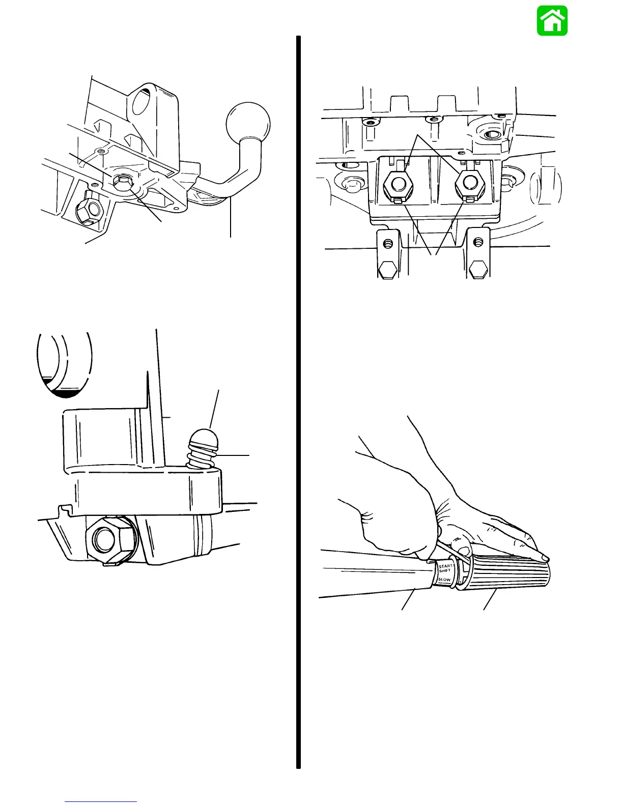
15. Bend tab washer away from bolt securing shift
lever and remove bolt and lever from bracket.
a
b
c
51622
a - Tab Washer
b - Bolt
c - Shift Lever
16. Remove spring and detent pin from bracket.
a
b
51621
a - Spring
b - Detent Pin
17. Bend tabs on tab washers away from nuts secur-
ing bracket to steering arm. Remove nuts, tab
washers and bracket from steering arm.
a
b
c
51621
a - Tab Washer
b - Nut
c - Steering Arm
Tiller Handle Disassembly
1. Using a flat tip screwdriver, carefully pry/push
rubber grip off tiller handle.
ab
51603
a - Grip
b - Tiller Handle

 Loading...


