90-830234R3 DECEMBER 1997 ATTACHMENTS/CONTROL LINKAGE - 7B-9
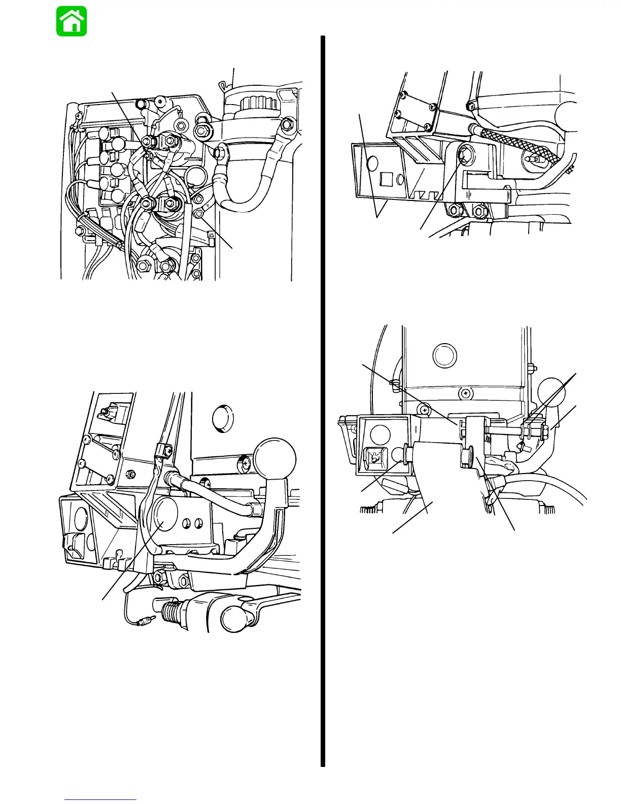
10. Disconnect BLUE/WHITE and GREEN/WHITE
trim leads from trim solenoids.
a
b
51622
a - BLUE/WHITE Lead
b - GREEN/WHITE Lead
11. Remove key switch, trim switch and their har-
nesses from tiller bracket.
12. Remove plug from tiller handle bracket.
a
51608
a - Plug
13. Remove bolt and nut (hidden) from tiller handle
bracket.
a
b
51625
a - Bolt
b - Nut (Hidden)
14. Remove tiller handle, 2 nylon bushings, stainless
bushing and 2 flat washers from bracket.
a
b
c
b
d
e
51606
a - Tiller Handle
b - Nylon Bushings (2)
c - Stainless Steel Bushing
d - Flat Washers (2)
e - Bolt

 Loading...


