7B-8 - ATTACHMENTS/CONTROL LINKAGE 90-830234R3 DECEMBER 1997
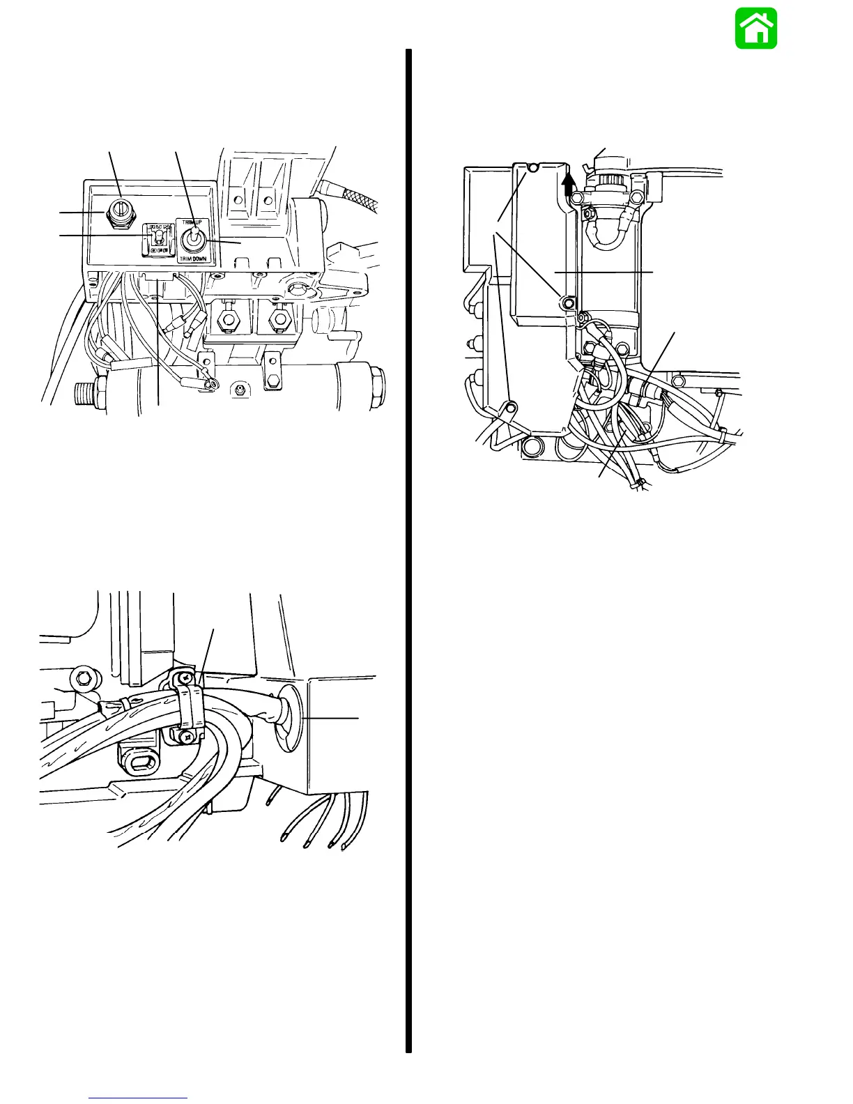
7. Remove nuts securing key switch and trim switch
to tiller handle bracket.
Remove clip securing lanyard stop switch and re-
move switch from bracket.
a
bc
d
e
a
51626
a - Nuts
b - Key Switch
c - Trim Switch
d - Clip
e - Lanyard Stop Switch
8. Remove harness retainer from outboard.
Remove grommet from tiller bracket.
a
b
51624
a - Harness Retainer
b - Grommet
9. Remove electrical panel access cover.
Disconnect switch harness from engine harness
plug.
Disconnect PURPLE bullet connector.
a
b
c
d
51621
a - Access Cover
b - Bolts
c - Switch Harness
d - PURPLE Lead

 Loading...


