90-830234R3 DECEMBER 1997 ELECTRICAL - 2B-17
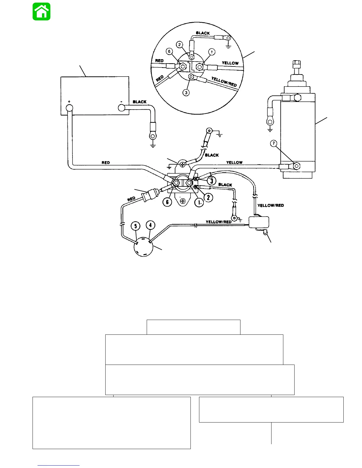
a - Battery
b - Starter Solenoid
c - Starter
d - Neutral Start Switch (Located in Control Housing)
a
b
c
d
e
f
g
e - Ignition Switch
f - Fuse Holder (If Equipped) (20 Amp Fuse)
g - Starter Solenoid
BLK = BLACK
BLU = BLUE
BRN = BROWN
GRY = GRAY
GRN = GREEN
PUR = PURPLE
RED = RED
TAN = TAN
VIO = VIOLET
WHT = WHITE
YEL = YELLOW
Starter Circuit
Starting Circuit Troubleshooting Flow Chart
Starter Motor Does Not Turn
SAFETY WARNING: Disconnect BLACK (starter motor)
cable from starter solenoid test point 1 BEFORE making
tests 1-thru-7 to prevent unexpected engine cranking.
TEST 1
Use an ohmmeter (R x 1 scale) and connect meter leads between
NEGATIVE (–) battery post and common powerhead ground.
No continuity indicated; there is an open circuit in the
BLACK negative (–) battery cable between the nega-
tive (–) battery post and the powerhead.
• Check cable for loose or corroded connections.
• Check cable for open.
Continuity Indicated
Proceed to TEST 2, on next page

 Loading...


