90-830234R3 DECEMBER 1997 ATTACHMENTS/CONTROL LINKAGE - 7B-13
12. Drive out drift pin and remove throttle gear from
throttle arm.
a
b
51602
a - Gear
b - Drift Pin
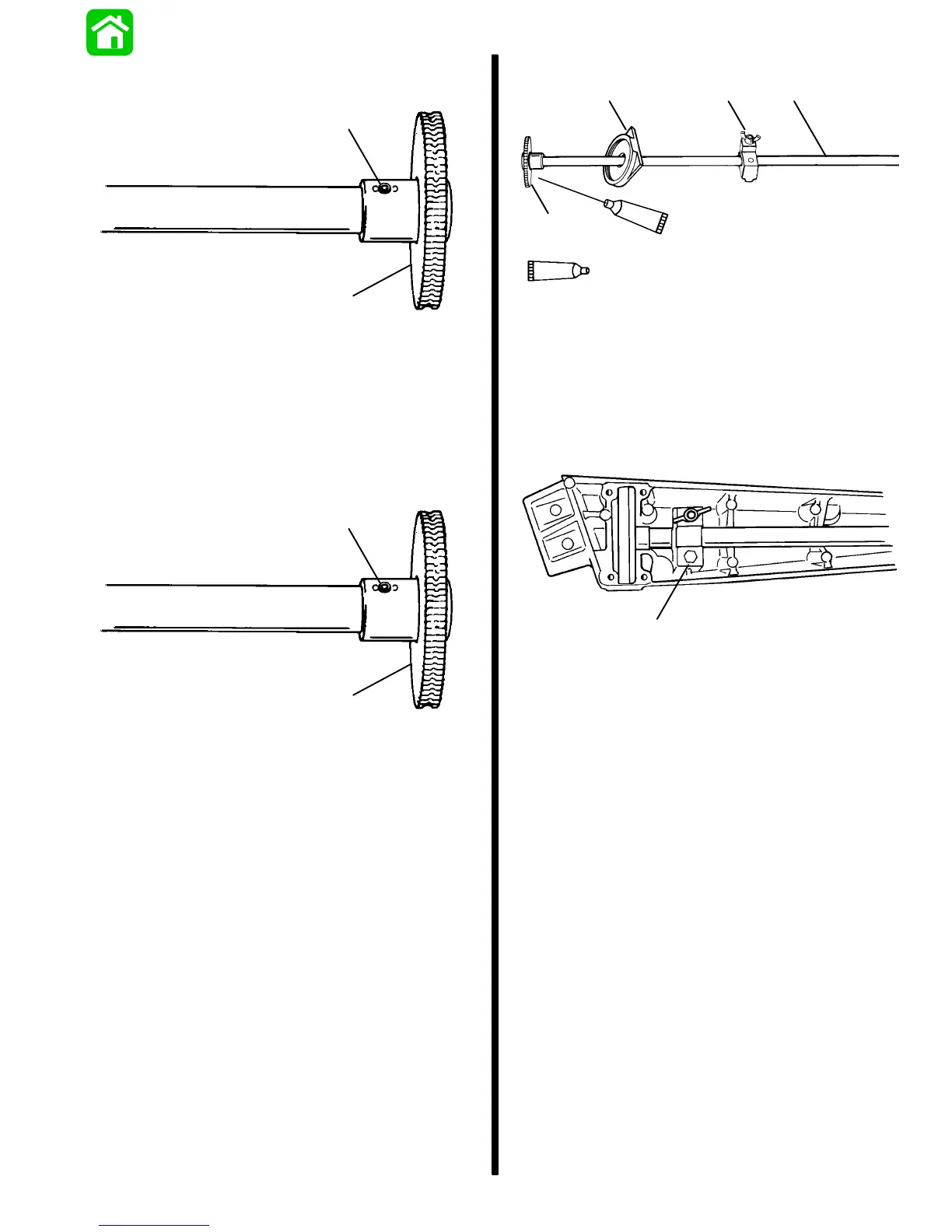
Tiller Arm Reassembly
1. Reinstall throttle gear on throttle arm and secure
gear to arm with new drift pin.
a
b
51602
a - Gear
b - Drift Pin
2. Apply a light coat of 2-4-C w/Teflon to gear teeth
and inside of gear cover.
3. Slide cover and friction device onto throttle arm.
a
b
cd
95
2-4-C With Teflon (92-825407A12)
51604
95
a - Throttle Arm
b - Gear
c - Throttle Friction Device
d - Cover
4. Install throttle arm assembly into tiller arm.
5. Torque friction device attaching bolt to 40 lb. in.
(4.5 Nm).
a
51604
a - Bolt [Torque to 40 lb. in. (4.5 Nm)]

 Loading...


