5A-22 - MID-SECTION 90-830234R3 DECEMBER 1997
Reference Views
a
b
c
d
e
f
e
g
h
i
j
95
2-4-C With Teflon (92-825407A12)
95
95
95
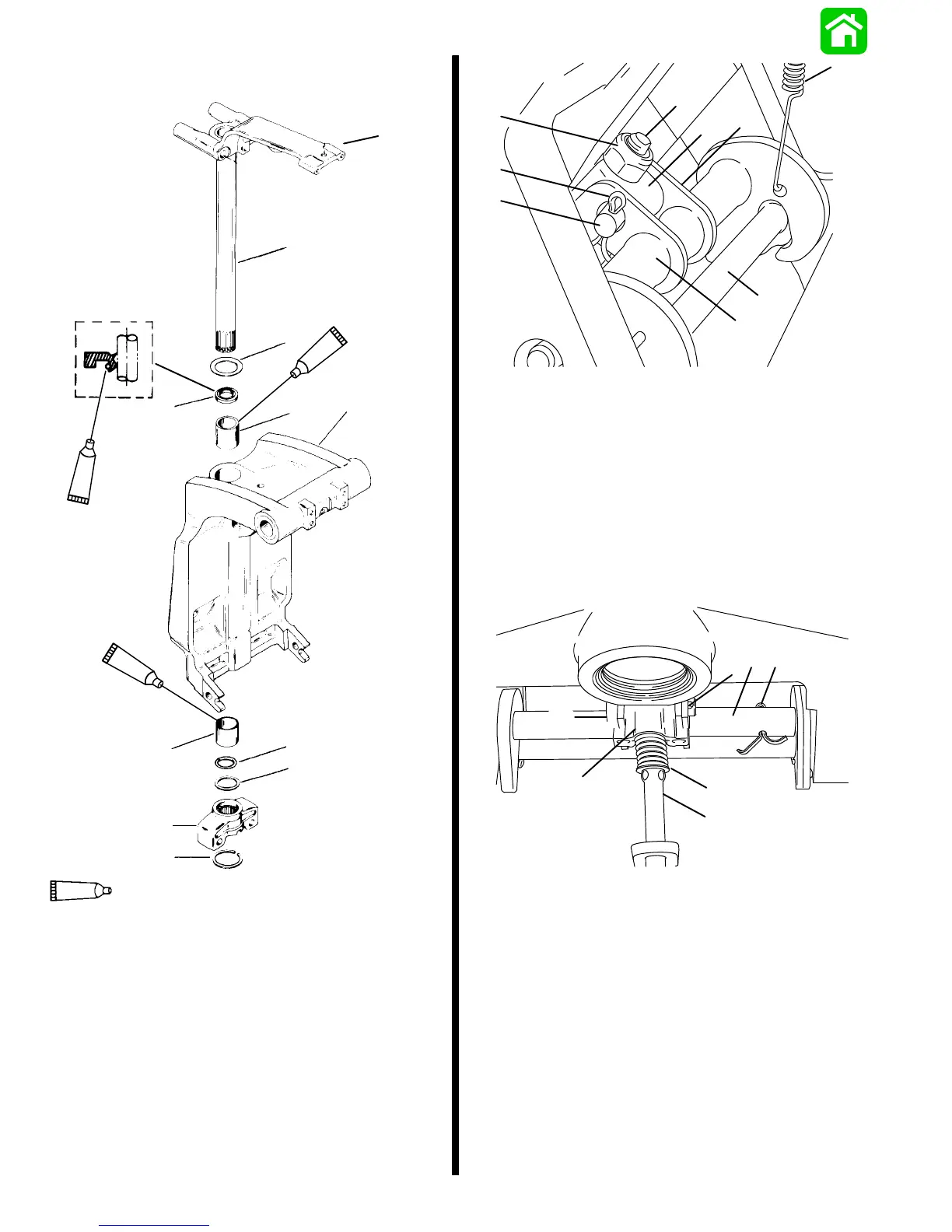
Steering Arm/Swivel Pin/Lower Mount Point
a - Steering Arm
b - Swivel Pin
c - Thrust Washer (Aluminum side towards swivel bracket)
d - Seal (Lips Face Down)
e - Bushing
f - Swivel Bracket
g - O-ring
h - Spacer
i - Yoke
j - Retaining Ring
21054
b
d
e
a
c
f
h
i
g
Non Power Trim Reverse Lock Hook
(Shown From Above)
a - Push Rod End
b - Nut
c - Push Rod Yoke
d - Cotter Pin
e - Clevis Pin
f - Reverse Lock Hook Shaft Arm
g - Reverse Lock Hook Shaft
h - Return Spring
i - Tilt Pin
21053
c
a
b
f
e
f
d
Non Power Trim Reverse Lock Hook
(Shown From Below)
a - Push Rod Shaft
b - Spring
c - Push Rod Yoke
d - Clevis Pin
e - Reverse Lock Hook Shaft
f - Cotter Pin (2)

 Loading...


