90-830234R3 DECEMBER 1997 ELECTRICAL - 2A-41
Ignition Coil Removal and
Installation
Refer to wiring diagrams in Section 2D when con-
necting wires.
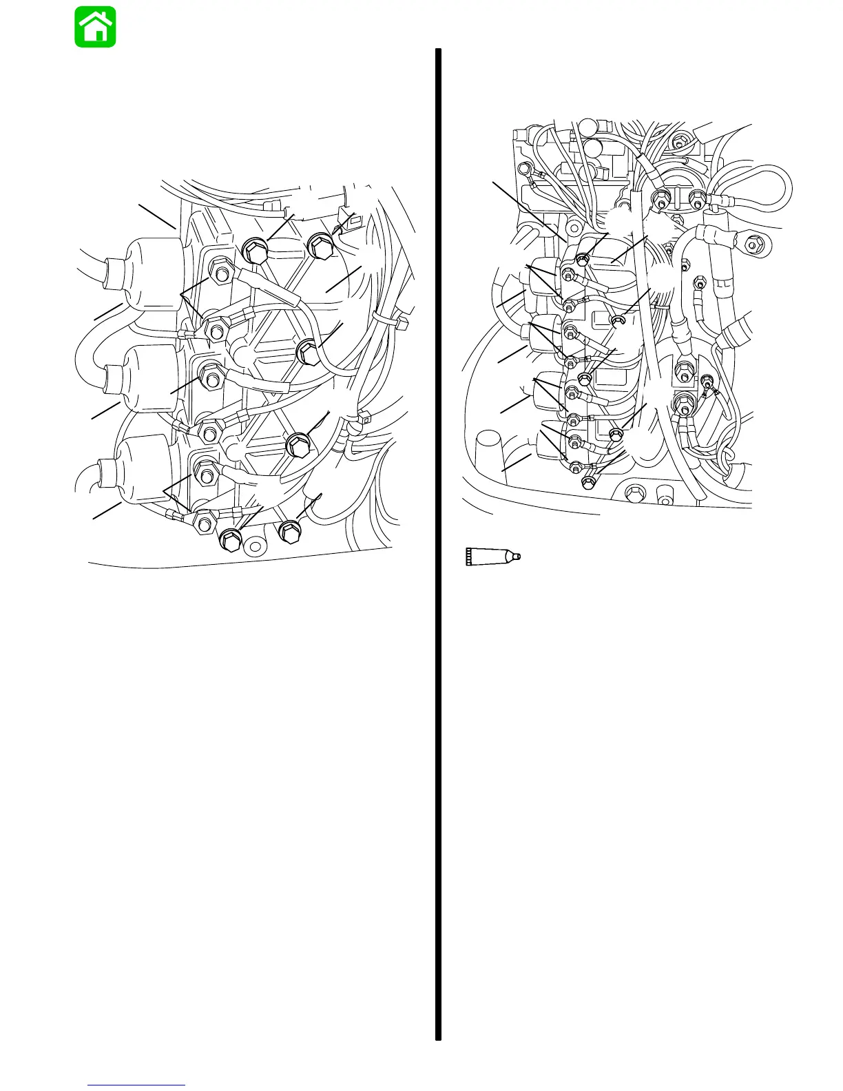
3 Cylinder Models
a
b
c
c
c
e
e
e
d
d
d
d
d
d
53974
a - Coils
b - Cover
c - Hex Nuts; coat with Quicksilver Liquid Neoprene
d - Bolts; torque to 20 lb. in. (2.3 Nm)
e - Coil Tower Boots; form a water tight seal between coil
tower and spark plug lead using Quicksilver Insulating
Compound
Refer to wiring diagrams in Section 2D when con-
necting wires.
4 Cylinder Models
a
e
e
e
e
b
c
c
c
d
d
d
d
d
Liquid Neoprene (92-25711--2)
53975
25
a - Coils
b - Cover
c - Hex Nuts; coat with Quicksilver Liquid Neoprene
d - Bolts; torque to 20 lb. in. (2.3 N·m)
e - Coil Tower Boots; form a water tight seal between coil
tower and spark plug lead using Quicksilver Insulating
Compound

 Loading...


