90-830234R3 DECEMBER 1997 ATTACHMENTS/CONTROL LINKAGE - 7B-7
Tiller Arm/Shift Lever
Removal
1. Remove battery cables from battery.
2. Remove outboard cowling.
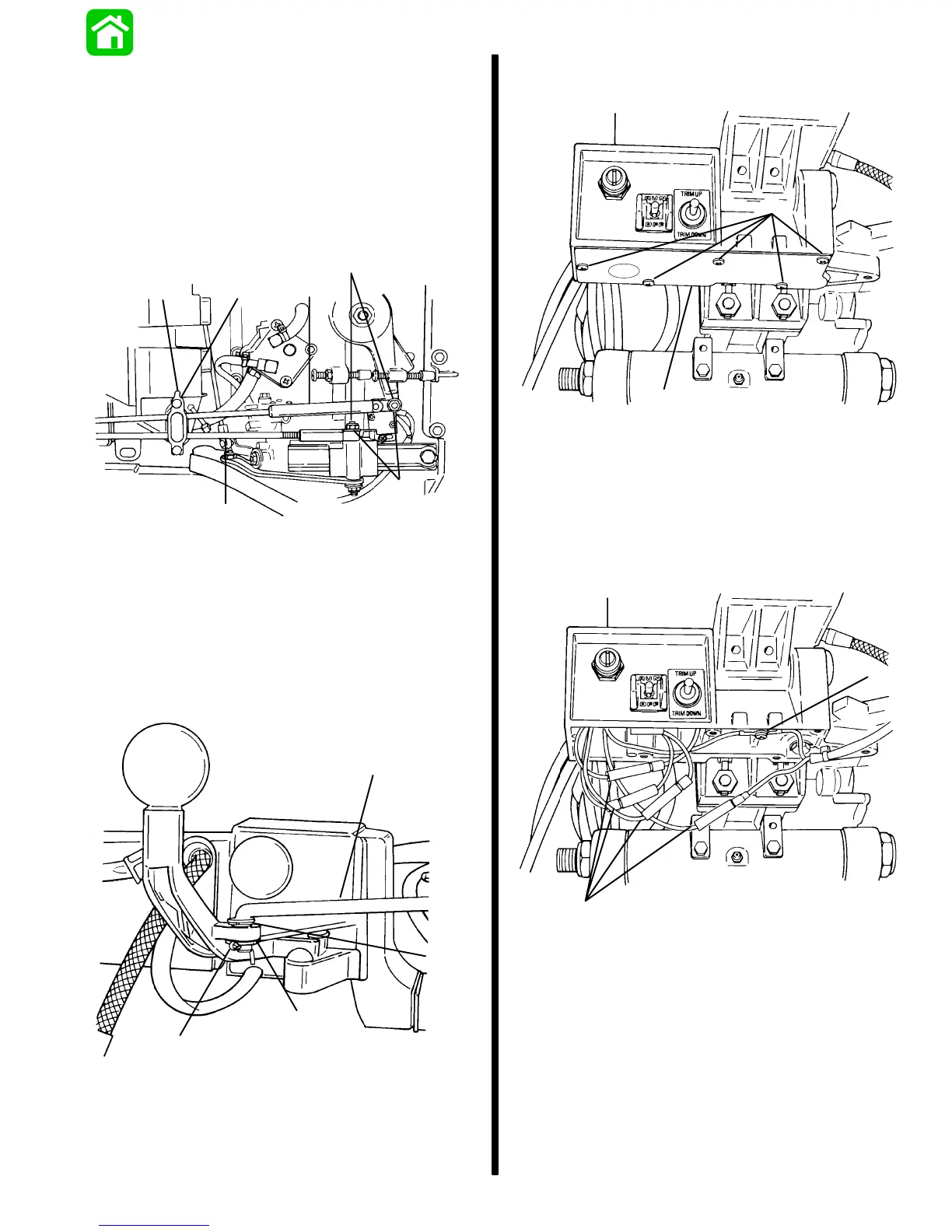
3. Remove nuts securing shift link rod and throttle
cable to engine. Release latch and remove shift
link rod and throttle cable from anchor bracket.
a
b
c
d
e
f
51620
a - Locking Nut
b - Washer
c - Shift Cable
d - Throttle Cable
e - Latch
f - Anchor Bracket
4. Remove cotter key, washer, bushing and shift link
rod from shift lever.
a
b
c
d
51624
a - Cotter Key
b - Washer
c - Bushing
d - Shift Link Rod
5. Remove access cover from underneath tiller
handle bracket.
a
b
51626
a - Access Cover
b - Screws
6. Disconnect key switch, lanyard stop switch and
tiller stop switch leads at bullet connectors.
Remove screw securing key switch and tiller stop
switch ground leads.
a
b
51626
a - Bullet Connectors
b - Screw

 Loading...


