2A-42 - ELECTRICAL 90-830234R3 DECEMBER 1997
Switch Box Removal and
Installation
Refer to wiring diagrams in Section 2D when con-
necting wires.
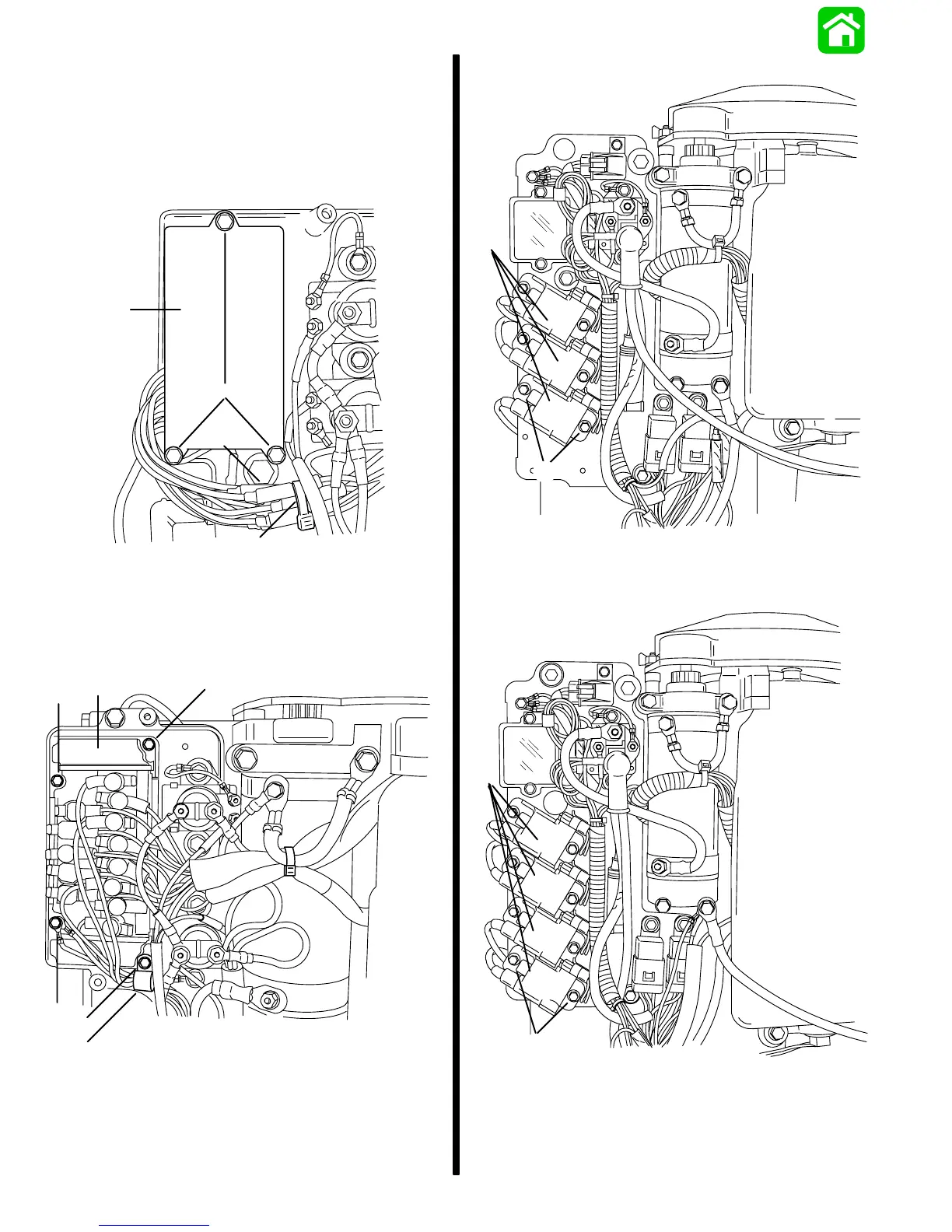
3 Cylinder Models
a
c
b
d
53971
a - Bolts [Torque to 40 lb. in. (4.5 N·m)]
b - Bullet Connectors
c - Sta-Strap
d - Switch Box
4 Cylinder Models
d
c
c
c
b
a
53970
a - Switch Box
b - J-Clip
c - Bolt [Torque to 40 lb. in. (4.5 N·m)]
d - Screw (Secure coil ground wires under screw)
3 Cylinder Models w/CDM Ignition
a
b
55418
a - CDM
b - Bolt – Torque to 60 lb. in. (6.8 N·m)
4 Cylinder Models w/CDM Ignition
b
a
55419
a - CDM
b - Bolt – Torque to 60 lb. in. (6.8 N·m)

 Loading...


