7A-10 - ATTACHMENTS/CONTROL LINKAGE 90-830234R3 DECEMBER 1997
a
b
c
b
d
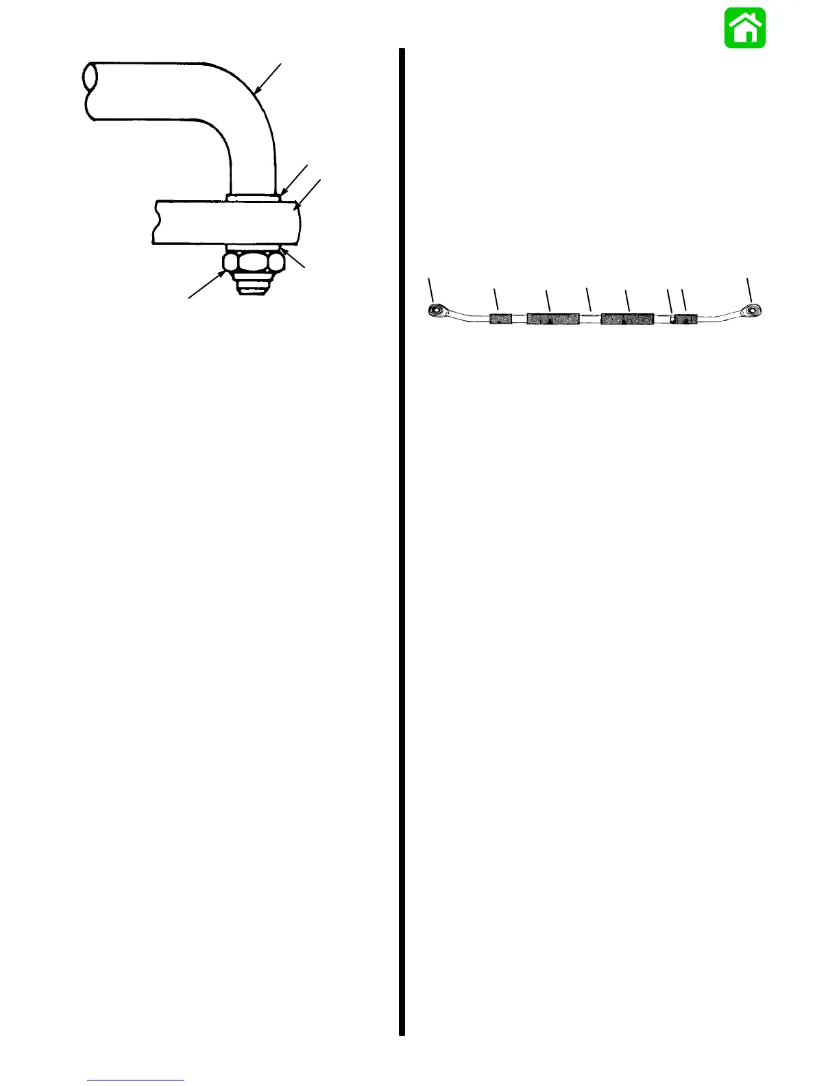
a - Steering Link Rod
b - Flat Washer (5/8″ O.D.)
c - Steering Cable End
d - Locknut; Tighten Until it Seats [DO NOT Exceed 120 lbs.
in. (13.6 Nm)], then Back Nut Off 1/4-Turn.
Figure 7. Steering Link Rod Assembled on
Steering Cable
7. Lubricate hole(s) in end of steering cable(s) with
2-4-C w/Teflon and assemble steering link rod(s)
to steering cable end, as shown in Figure 7. Tight-
en self-locking nut until it seats [DO NOT exceed
120 lbs. in. (13.6 Nm)], then back nut off
1/4-turn.
Steering Eyes and Coupler Installation
1. Position engines so that they are facing straight
forward. (Distance between centers of threaded
pivot bolt holes in engine steering arms must be
equal to distance between propeller shaft cen-
ters.)
2. Lubricate inside of rubber sleeves (Figure 8) and
slide onto coupler.
3. Slide rubber bushings (Figure 8) onto steering
eyes.
e
a
c
d
b
a
e
b
51520
a - Rubber Bushing
b - Rubber Sleeve
c - Jam Nut; Torque to 20 lbs. ft. (13.6 N·m)
d - Coupler
e - Steering Eye
Figure 8. Coupler Assembled

 Loading...


