90-830234R3 DECEMBER 1997 ELECTRICAL - 2B-23
2. If removed, reinstall parts on armature shaft. Use
a new locknut and tighten securely on end of
shaft.
e
f
g
dc
b
a
11658
a - Locknut
b - Spacer
c - Spring
d - Drive Assembly
e - Drive End Cap
f - Armature Shaft
g - Washer
3. Lubricate helix threads on armature shaft with a
drop of SAE 10W oil.
4. Lubricate bushing in drive end plate with a drop
of SAE 10W oil.
5. Position armature into starter frame.
6. To prevent damage to brushes and springs when
installing commutator end cap, it is recom-
mended that a brush retaining tool be made as
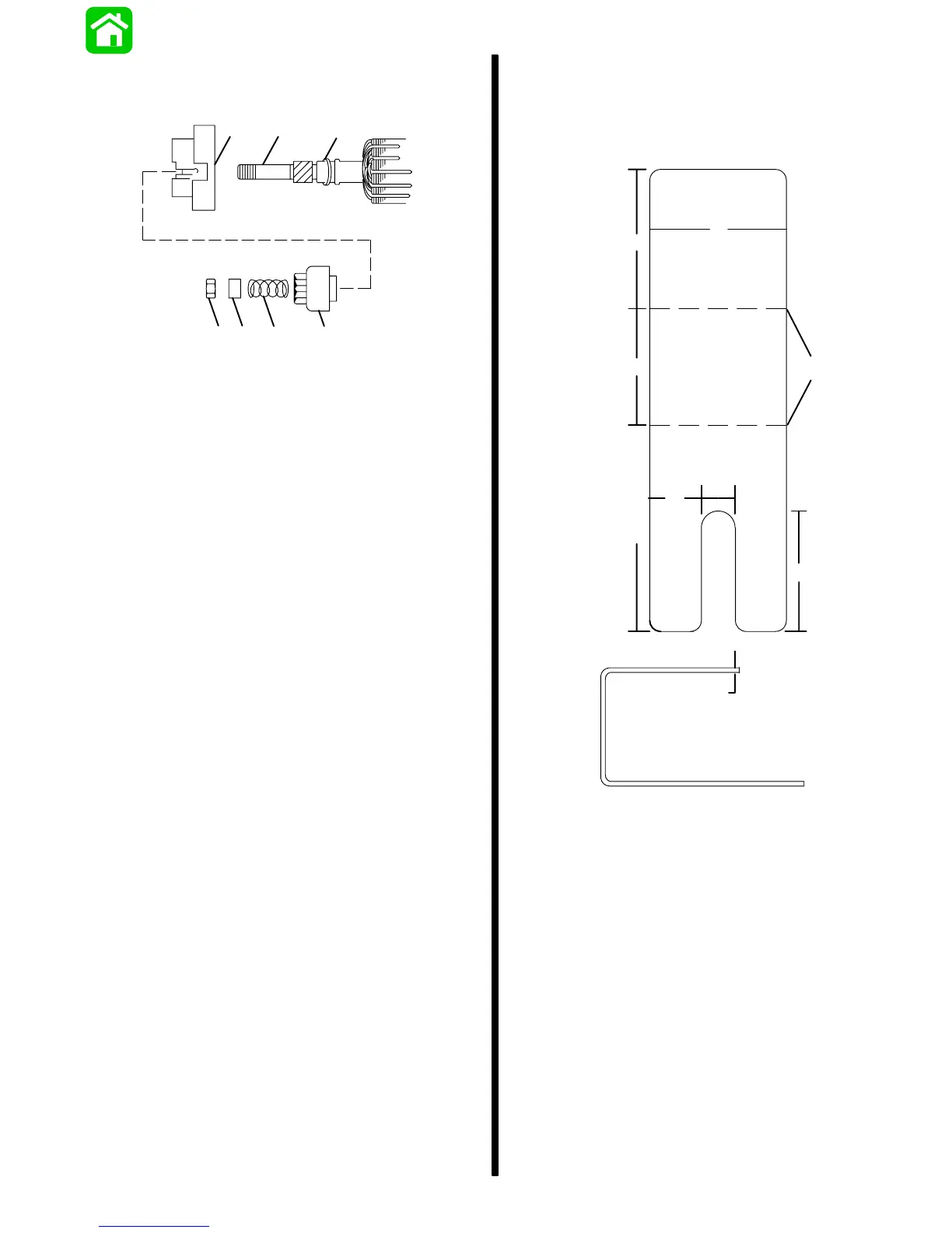
shown:
90 Bend
2”
2”
1-11/16”
3”
3/4”
1/2”
1-3/4”
b
a
a - Brush Retainer Tool Layout (Full Size)
b - 18-Gauge Sheet Metal
7. Lubricate bushing (located in commutator end
cap) with one drop of SAE 10W oil. DO NOT over
lubricate.
8. Place springs and brushes into brush holder and
hold in place with brush retainer tool.

 Loading...


