2B-24 - ELECTRICAL 90-830234R3 DECEMBER 1997
a
b
11661
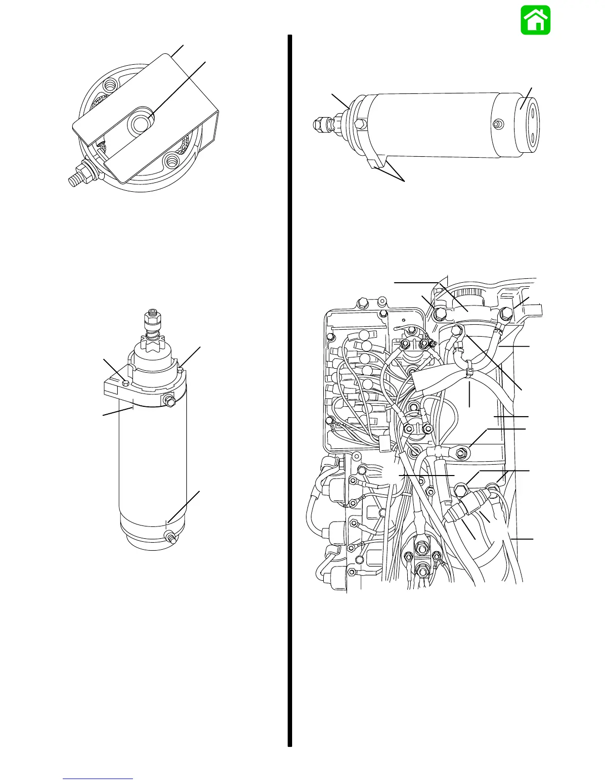
a - Brush Retainer Tool
b - Bushing (DO NOT Over Lubricate)
9. Install armature into starter frame and align
match marks. Install commutator end cap onto
starter frame and align match marks. Remove
brush retainer tool. Install through bolts and
torque to 70 lb. in. (7.9 N·m).
c
b
a
c
11646
a - Alignment Marks
b - Alignment Marks
c - Bolts [Torque to 70 lb. in. (7.9 N·m)]
INSTALLATION
1. Install 2 rubber collars and 2 rubber bumpers.
b
a
a
11645
a - Rubber Collars
b - Rubber Bumpers
2. Install components as shown.
3. Connect battery leads to battery.
k
i
h
g
b
f
e
c
d
b
a
j
b
54159
a - Clamp, upper
b - Bolts [Torque to 14.5 lb. ft. (19.7 N·m)]
c - Bolt and Lockwasher
d - BLACK Cable
e - Sta-strap
f - Starter
g - YELLOW Cable [Torque nut to 60 lb. in. (6.8 N·m)]
h - Clamp, lower
i - BLACK Negative (-) Battery Cable
j - J-Clip
k - Fuse Holder

 Loading...


