90-830234R3 DECEMBER 1997 LOWER UNIT - 6A-27
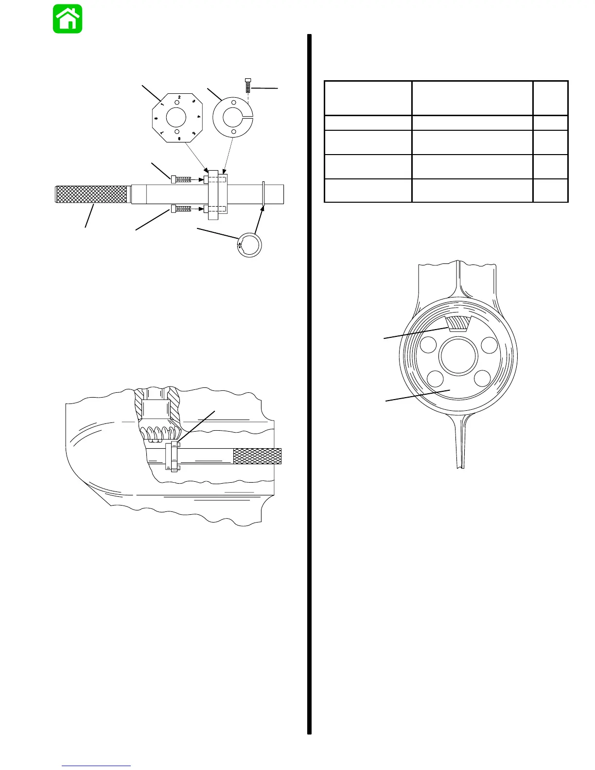
6. Assemble Pinion Gear Locating Tool (91-12349A2)
as shown; do not tighten collar retaining bolt at
this time.
b
d
e
c
ca
f
a - Arbor
b - Gauging Block; Install With Numbers Away From Split
Collar
c - Bolt; Gauging Block Retaining
d - Split Collar
e - Bolt; Collar Retaining
f - Snap Ring
7. Insert tool into forward gear assembly; position
gauging block under pinion gear as shown.
a
22067
a - Gauging Block
8. Remove tool, taking care not to change gauging
block position, and tighten collar retaining bolt.
9. Insert tool into forward gear assembly; position
proper numbered flat (from chart) of gauging
block – under pinion gear.
MODEL
GEAR RATIO
(PINION GEAR TEETH/
REVERSE GEAR TEETH)
USE
FLAT
NO.
50 Bigfoot (4-stroke) 13/30 8
60 Bigfoot/60 Sea-
pro/60 Marathon
13/30 8
75-thru-90
(3 Cylinder)
13/30 8
100/115/125
(4 Cylinder)
14/29 2
10. Install the number “3” locating disc against bear-
ing carrier shoulder in gear housing.
11. Position access hole as shown.
b
a
24643
a - Locating Disc
b - Access Hole

 Loading...


