90-830234R3 DECEMBER 1997 ATTACHMENTS/CONTROL LINKAGE - 7B-15
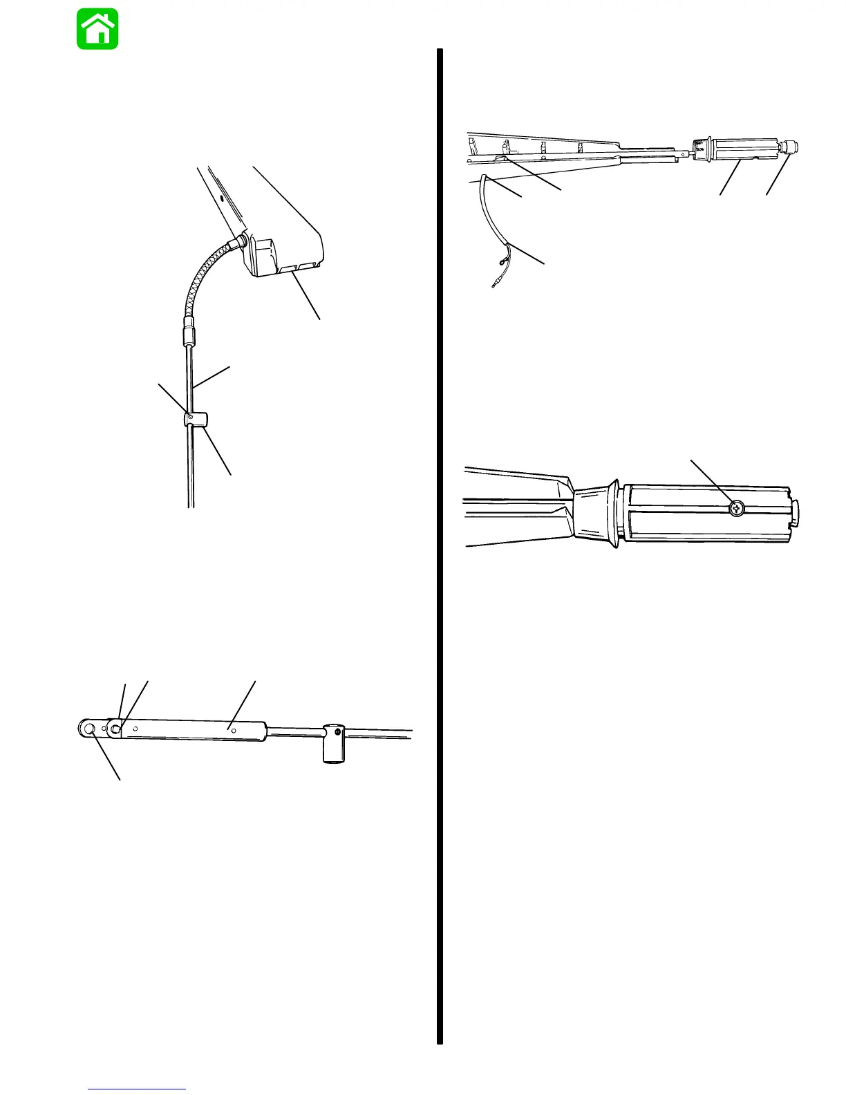
11. Slide brass barrel over throttle cable tube. Se-
cure barrel to tube with allen screw approximate-
ly 3.5 in. (89mm) from stainless conduit. DO NOT
OVERTIGHTEN screw as tubing may be crushed
binding throttle cable. Position barrel to face to-
wards tiller handle.
a
b
c
d
51607
a - Brass Barrel
b - Tube
c - Allen Screw
d - Tiller Handle
12. Install throttle cable guide onto throttle cable. Se-
cure guide to cable with anchor and two screws.
Guide hole should face up.
ab
c
b
51602
a - Cable Guide
b - Screws (2)
c - Hole (faces up)
13. Position throttle arm slot to face stop harness exit
hole in tiller handle. Route stop switch harness
through twist grip, into throttle arm, and out
through side of tiller handle.
a
b
c
de
51602
a - Slot
b - Exit Hole
c - Harness
d - Twist Grip
e - Stop Switch
14. Secure twist grip to throttle arm with attaching
screw.
a
51603
a - Screw
15. Sta-strap harness to throttle arm.
IMPORTANT: Allow enough slack in harness (ro-
tate throttle grip in both directions) before secur-
ing harness to handle assembly with J-clip.
16. Attach harness to tiller arm with J-clip allowing
enough slack in harness for full throttle rotation.

 Loading...


