90-830234R3 DECEMBER 1997 ATTACHMENTS/CONTROL LINKAGE - 7B-17
3. Insert bushings and thrust washer into shift lever.
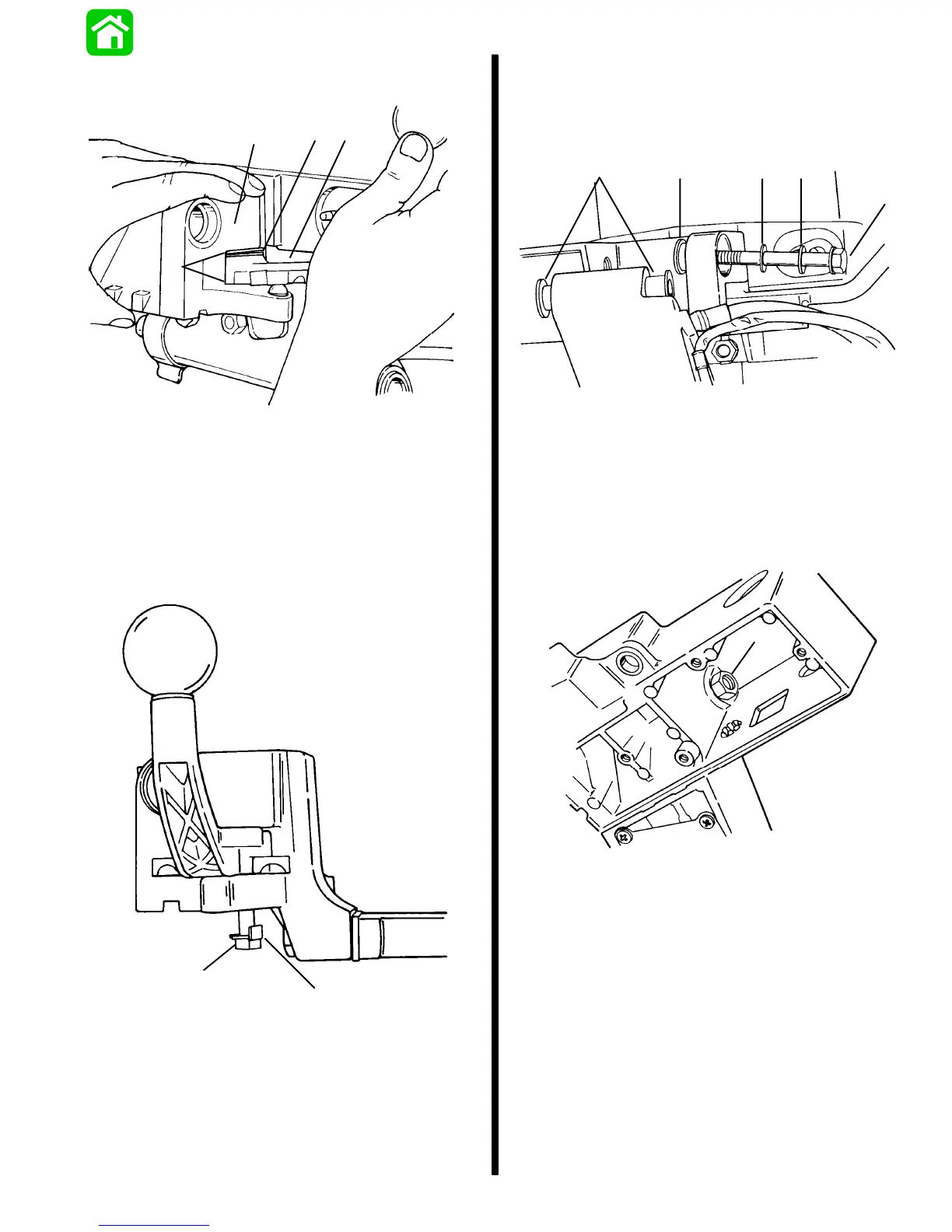
Install shift lever onto bracket.
a
bc
d
51620
a - Bushings
b - Thrust Washer
c - Shift Lever
d - Bracket
4. Secure shift lever to bracket with bolt and NEW
tab washer. Align tab washer with slot in bracket.
Torque bolt to 110 lb. in. (12.4 Nm).
a
b
51620
a - Bolt
b - Tab Washer
5. Install two nylon bushings into tiller handle.
Install stainless bushing into bracket.
Install tiller handle to bracket using bolt and two
washers.
ab
c
de
51622
a - Nylon Bushings
b - Stainless Bushing
c - Bolt
d - Washer (Thin)
e - Washer (Thick)
6. Secure bolt in place with nut. Torque nut to 40 lb.
ft. (54.2 Nm).
a
51623
a - Nut

 Loading...


