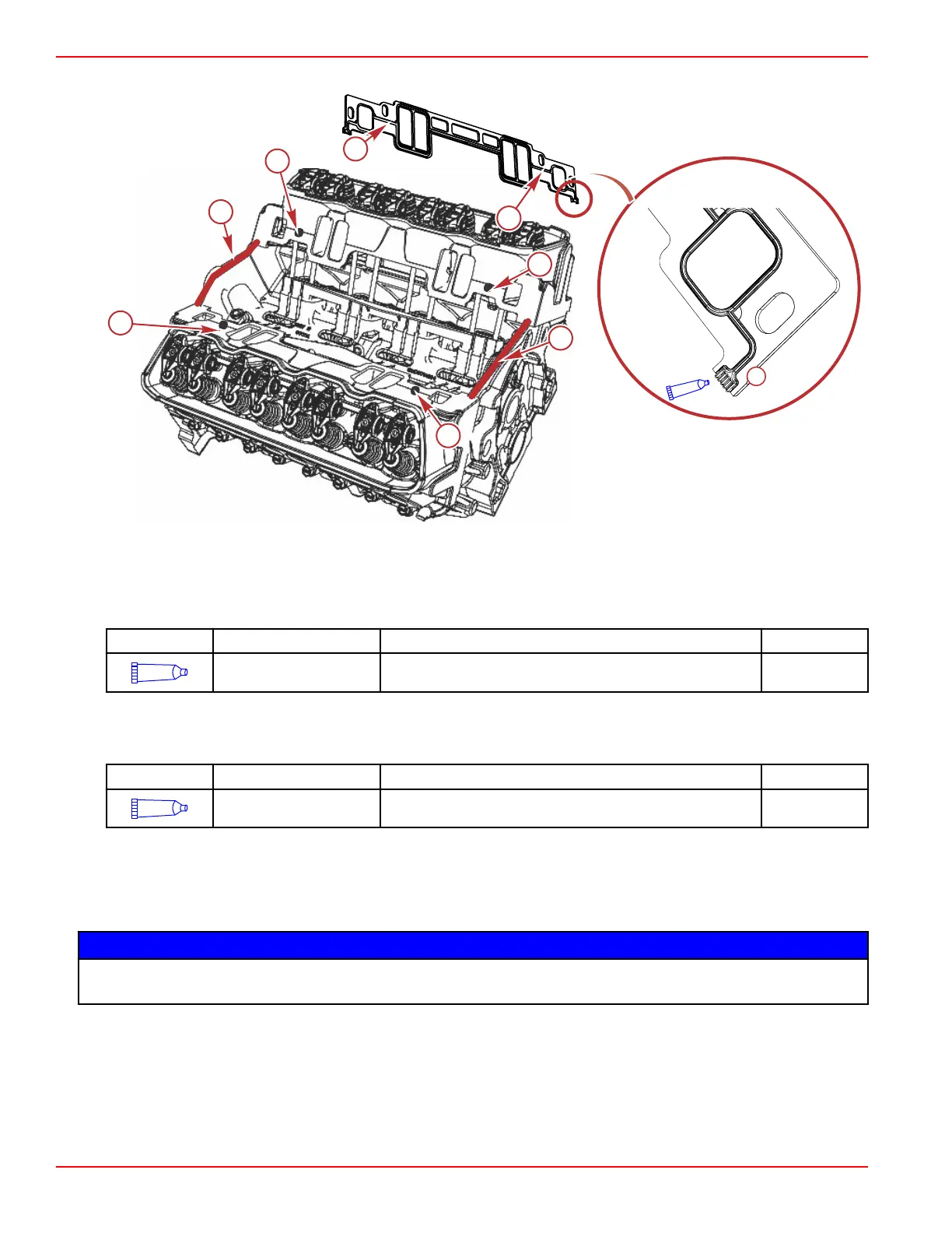
2. Align the intake manifold gaskets with the locator pins. Install the lower intake manifold gaskets onto the cylinder heads.
a - Locator pin hole
b - Locator pins
c - Area for sealant
Tube Ref No. Description Where Used Part No.
128
Loctite 5900 Ultra Black
RTV Silicone Sealant
Each end of the lower intake manifold gaskets on the
cylinder head side
92-809826
3. Apply a 5 mm (0.197 in.) wide bead of adhesive to the front and rear of the engine block as shown. Extend the adhesive
bead 13 mm (0.51 in.) up on the intake gaskets.
IMPORTANT: Do not get sealer into the oil sending unit hole at the rear of the engine.
Tube Ref No.
Description Where Used Part No.
128
Loctite 5900 Ultra Black
RTV Silicone Sealant
A wide bead of adhesive to the front and rear of the engine
block, extending the adhesive bead
92-809826
4. Coat the threads of the intake manifold bolts with sealant.
5. Carefully install the intake manifold assembly onto the engine block.
IMPORTANT: Avoid engine damage. Crankshaft bearing bore alignment may become distorted resulting in damage to the
crankshaft bearings if intake manifold fastener tightening sequence and torque are done improperly. Always torque the
bolts in sequence to the specified amount in each of the passes required.
NOTICE
The crankshaft bearings are matched sets. Mismatching the bearings can result in engine damage. Replace and install the
bearings in matched pairs.
Engine Inspection and Assembly
Page 3B-60 © 2016 Mercury Marine 90-8M0099748 eng DECEMBER 2015

 Loading...


