c. Turn the flywheel in the direction of normal engine rotation and measure flywheel runout at the smooth outer edge of
the flywheel just inside the ring gear.
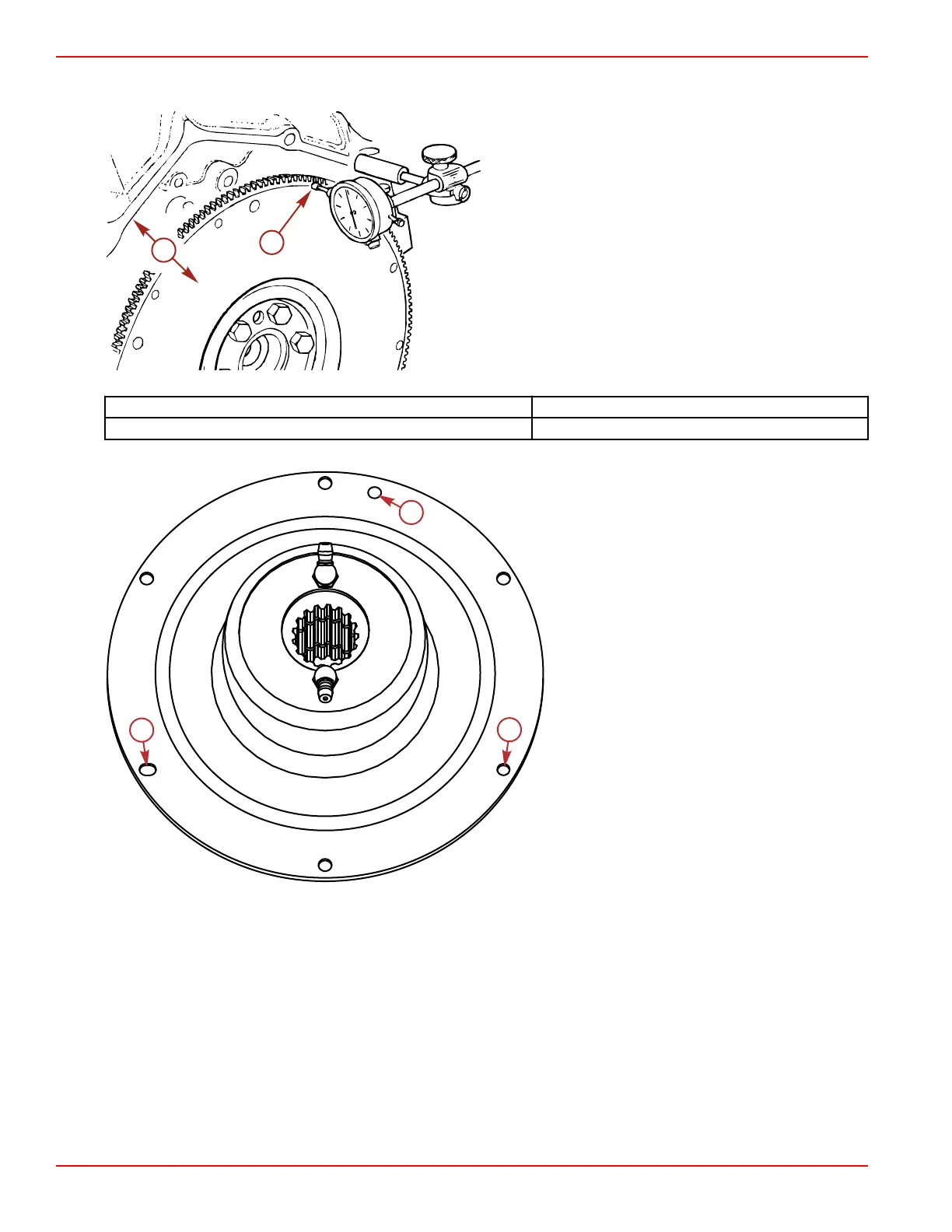
a - Dial indicator
b - Runout measurement
Description 6.2 Liter (377 cid)
Runout 0.203 mm (0.0080 in.) maximum
4. Assemble coupler to the flywheel using six screws and washers, driving them loosely into place.
a - Slotted hole used for alignment
b - Small hole tightly held diameter, used for
alignment
c - This hole is used for manufacturing, not for
assembly
5. Run the heads of the screws down flush with the coupler, but do not tighten any of them at this point. This will allow the
alignment holes to locate the coupler.
Engine Inspection and Assembly
Page 3B-64 © 2016 Mercury Marine 90-8M0099748 eng DECEMBER 2015

 Loading...


