8 - ATTACHMENTS AND OPTIONAL EXTRA
8 - 4
ASSEMBLY OF ATTACHMENTS WITH QUICK-COUPLING
- a standard loader has been chosen to illustrate the operations required for the installation of a quick-coupling attachment;
the following operations apply to any attachment manufactured by Merlo that is equipped with the same coupling system.
- read and make sure to understand all the instructions regarding the attachment you purchased, which are provided either in
the following paragraphs or in the attached manual. Pay particular attention to safety warnings and to any notes on how to
install and handle the attachment.
- make sure that the equipment is resting on a compact flat surface, and that it cannot accidentally topple over
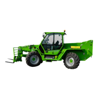
- drive your machine close to the couplings of attachment "A", with the carriage rotated downwards (Fig. 1).
- slightly raise the telescopic boom (Fig. 2).
- activate the control to lift the quick-coupling piston "P" (see paragraph "MAIN DISTRIBUTOR LEVER", in the chapter
"CONTROLS AND INSTRUMENTS"), while at the same time rotating the carriage upwards, so as to hitch the attachment
(Fig. 3)
- release button on the control joystick
- raise the telescopic boom by about 1.5 metres, and check that quick coupling cylinder "P" is correctly engaged in its locking
position on the carriage.
WARNING! Keep people away from the surrounding area when installing equipment. Consult the data plates
inside the driver's cab so that the machine's load limits in relation to the various positions of the boom are not
exceeded.
Before starting the assembly of the attachments with quick coupling, make sure that the machine's carriage does not
have any attachment fitted.
Never position yourself underneath the attachment to check the correct insertion of the locking pin.
Do not use the attachment if the locking pin is not correctly inserted.
Lower the telescopic boom and repeat the procedure.
- stop the diesel engine
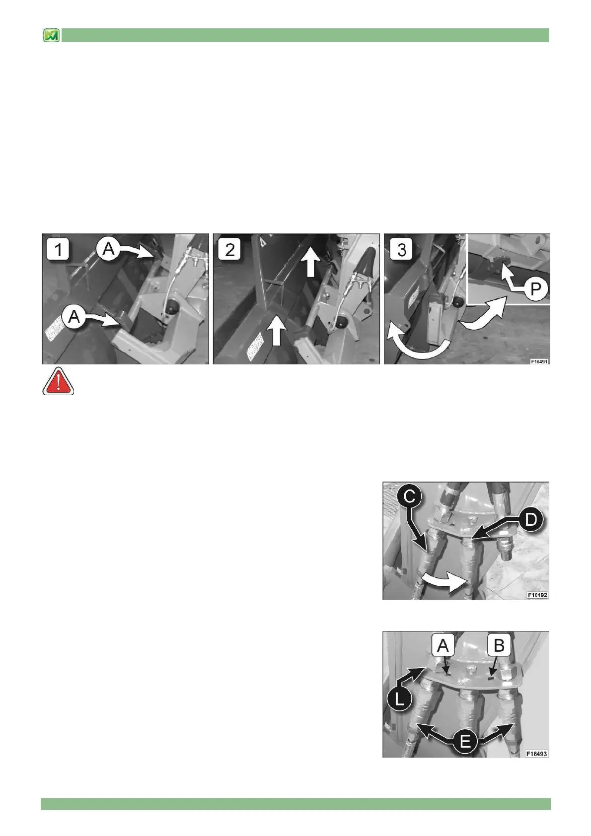
- unscrew the ring nut from quick coupling [A], and disconnect hose "C" that
feeds the quick coupling cylinder "P"
- connect hose "C" to coupling "D"; this prevents the attachment from
accidentally uncoupling from the carriage if the quick-coupling cylinder "P" is
unintentionally operated.
HYDRAULIC CONNECTION OF QUICK-COUPLING ATTACHMENTS
Should the attachment installed on the carriage feature hydraulically controlled
functions, connect hoses "E", from the attachments, to the quick couplings
marked with letters [A] and [B], on metal sheet "L".
The connection diagram, also shown on the joystick sticker in the cab, foresees
that the quick coupling marked with the letter [A] must be used for the oil delivery
to the attachment, while the quick coupling marked with the letter [B] must be
used for the oil return. (see also paragraph "CONTROL JOYSTICK" chapter
"CONTROLS AND INSTRUMENTS").