4 - COMMANDS AND INSTRUMENTS
4 - 16
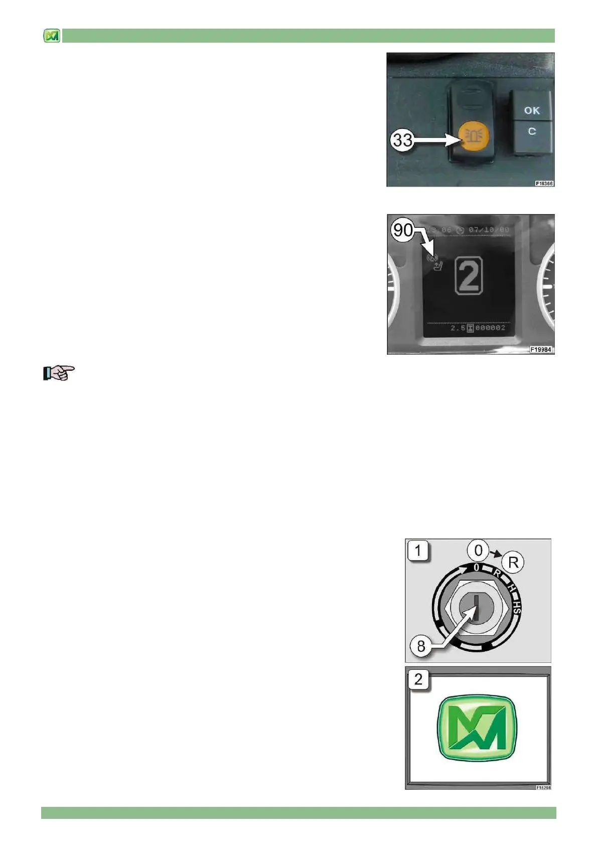
• FLASHLIGHT ON ROOF (33)
Press the switch (33) to activate the rotary flashlight on the cab roof.
For the use of the flashlight, respect the regulations for road use given in
"COMMAND STICKERS - LEAFLETS IN THE CAB".
HYDROSTATIC TRANSMISSION LOCK (90)
If the operator decides to leave the driving can with the engine ON and the parking
brake not engaged, the machine automatically set a safe mode by locking the
hydrostatic transmission.
In order to resume using the hydrostatic transmission for machine forward / reverse
manoeuvres, the operator must sit correctly on the seat in the cab.
If the operator decides to leave the driving can with the engine ON and the
direction selector (20) in position "F" or "R", the hydrostatic transmission is reset by
placing the selector switch (20) in neutral position "N" and then in the position for
the required direction.
If the operator forgets to engage the parking brake before leaving the machine, a
flashing yellow signal (90) warns this non-conforming use situation.
NOTE! Correct and safe use of the machine requires the following steps before leaving the driving cab:
• place the gear selector (19) in the neutral position "N"
- place the direction selector (20) in neutral position "N"
• engage the parking brake (37)
- switch off the machine's diesel engine
- leave the driving cab and close the cab door
The automatic lock of the hydrostatic transmission described in this paragraph must be considered as an exceptional
case and not a routine procedure.
DYNAMIC LOAD CONTROL SYSTEM (M-CDC)
(only for models P37.12PLUS – P38.12PLUS – P38.13PLUS – P38.14PLUS – P40.9PLUS – P40.17PLUS – P60.10 – P72.10)
• INTRODUCTION
The dynamic load control system constantly checks the longitudinal stability of your
machine in relation to the load lifted on the carriage, the position of the telescopic
boom and the attachments installed in order always to ensure maximum machine
operating safety for the operator.
The following paragraphs provide all the instructions for correct operation of the
dynamic load control system installed on your machine. Inasmuch, pay very close
attention to this information before using the machine.
• DISPLAY NOMENCLATURE (D)
When the instrument panel is switched on (starter key (8) in position "R") (FIg.1), the
system displays a screen for 3 seconds with the MERLO logo (Fig.2) and then
automatically opens the main screen.