10 - ELECTRICAL SYSTEM
10 - 3
FUSES
Electrical circuits are protected by fuses and relays located in the ENGINE COMPARTMENT and COVER "7" in the cab (see
paragraph COVERS in section "ORDINARY MAINTENANCE"). If a fuse blows, first find the cause and then replace it with a
new one with the same features.
If any accessories on request have been ordered, the affected fuses are placed on the side of the general one.
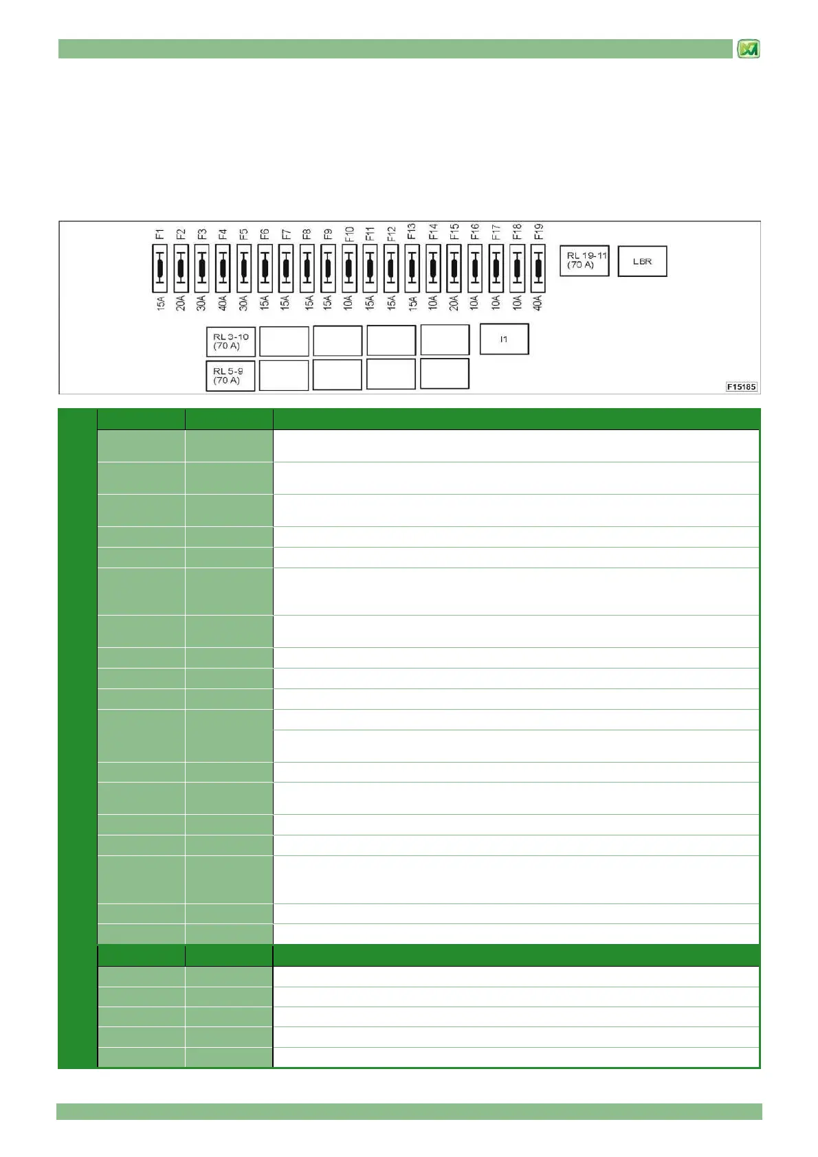
• FUSES IN COVER 7
FUSE
Position Type Description
F1 15A
Power supply UAE
Starting key
F2 20A
Electric socket inside cab (25A)
Portable light socket (cigarette lighter)
F3 30A
Air conditioning compressor clutch
Direct power supply for accessories (BVC)
F4 40A Glowplug (if present)
F5 30A Power supply starting motor relay
F6 15A
Car-radio (fitting)
Optional cab connector
Power supply accessories under key (BSC)
F7 15A
Joy-stick supply
UAE signal
F8 15A Horn
F9 15A Beam lights
F10 10A Lower beam lights
F11 15A Fitted for rear work lights on cab (on request)
F12 15A
Hazard light
2nd hazard light (if present)
F13 15A Fitted for front work lights on cab (on request)
F14 10A
Car-radio fitting
Cab light
F15 20A Cab air circulation electro-fan
F16 10A Direction indicator flasher power supply
F17 10A
Roof wiper (upon request)
Front and rear wiper
Direct accessory power (BD)
F18 10A Power supply UPD
F19 40A Power supply UCM
RELAYS AND
BLINKING
Position Type Description
I1 Direction lights blinker, emergency lights
LBR Flat battery restoring
RL 5-9 70A Starter motor
RL 19-11 70A UAE signal and Output UCM power supply
RL 3-10 70A Air conditioning compressor