4 - COMMANDS AND INSTRUMENTS
4 - 33
STABILISER COMMAND SWITCHES (135)
(only for P38.12 PLUS – P38.13 PLUS – P38.14 PLUS – P40.17 PLUS – P38.12 – P38.13 – P38.14 – P40.17 – P38.13EE –
P40.17EE)
The machine is equipped with a stabilising system consisting of 2 ground
supports.
The maximum load transmitted to the ground by each stabiliser is indicated on
each stabiliser itself by a specific sticker. Additional load distributing systems are
required if the ground is not solid.
The general operating conditions of this device are the following:
- carry out the machine stabilising operations on a sufficiently firm and
compact ground
- stabilise the machine at a standstill and with all 4 tyres resting correctly on
the ground
- place the gear selector (19) and drive direction (20) to neutral "N"
- lower the telescopic boom within the safety limit;
The machine can be considered to be stabilised when the front tyres are raised
off the ground. The dynamic load control display (D) in the cab must show the
symbol with the machine on stabilisers in field (221).
WARNING! Always work with the utmost care, especially when
handling loads. If this is the case, please make sure that the load falls
within the limits of the corresponding load chart, so as to prevent the
machine stability control system to step in with a consequent block of all
controls.
It is possible to lift loads on an uneven ground by correctly stabilising the machine in order to return it to the initial
operating conditions. Before proceeding to any lifting operation, check that the machine is correctly levelled using the
spirit-level (13) located in the cab.
If during operation with lowered stabilisers the machine needs to be supported on the wheels, it is necessary to check
that the weight of the load to be lifted falls within the limits for operations on wheels, as outlined in the machine's load
chart; such manoeuvres are otherwise prevented by the stability control system. Before performing this operation, it
is in any case advisable to lower and retract the telescopic boom completely.
To move stabilisers up or down, press and hold down the dedicated button. The movement execution speed is set with a
proportional ramp and reaches maximum speed within about 3 seconds of pressing the control. To make small stabiliser
movements, press the control switches briefly.
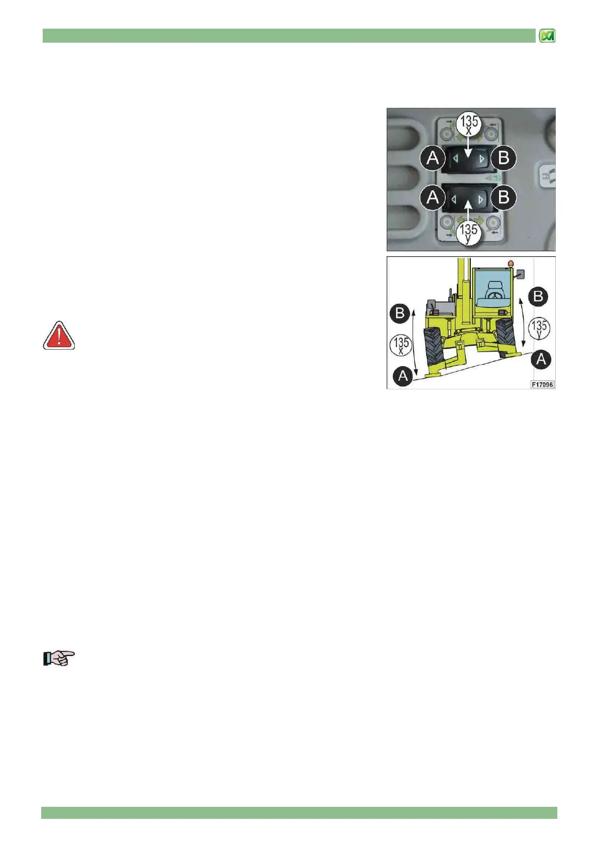
SWITCH REF. 135-X
A = right stabiliser descent
B = right stabiliser lifting
SWITCH REF. 135-Y
A = left stabiliser descent
B = left stabiliser lifting
IMPORTANT!
If the machine boom is raised beyond the safety limit, operating the stabilisers is prevented by a specific device.
END OF SECTION