5 - OPERATING INSTRUCTIONS
5 - 2
INTRODUCTION
This chapter provides the instructions for using your machine as a variable reach fork lift truck. Please follow the instructions
below very carefully, so as to ensure efficiency and utmost safety while working.
GENERAL INFORMATION
- when manoeuvring the loads never exceed the limits set in the load chart
- do not use counter-weights to alter the limits of the load chart
- never leave your machine unattended while the engine is running or when loads are hanging
- lifting people on the machine is absolutely forbidden if no platform, homologated and approved by Merlo S.p.A., is installed
- carrying a second operator on-board the machine is absolutely prohibited.
STANDARD FORKS ASSEMBLY
Standard forks are part of the standard equipment of your machine.
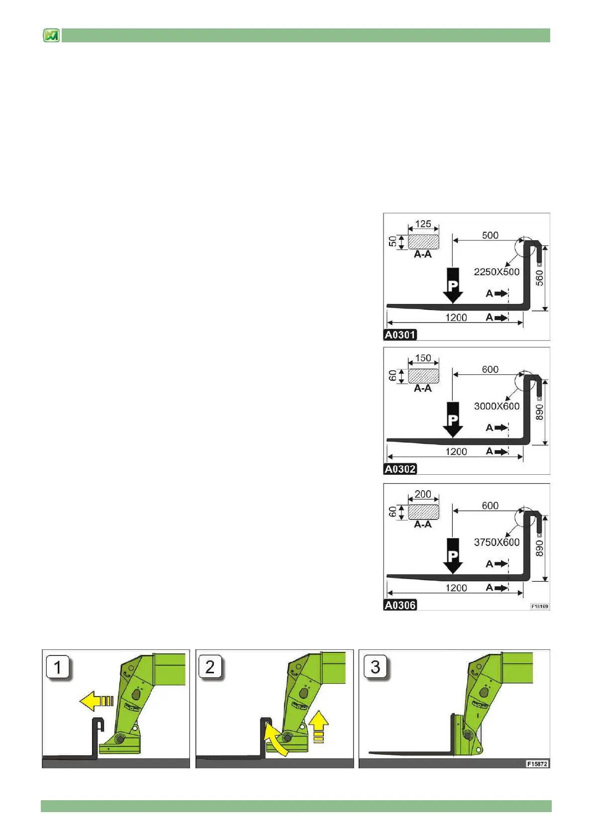
• TECHNICAL DATA OF STANDARD FORKS
For machines (P38.12 PLUS – P38.13 PLUS – P38.14 PLUS – P40.9 PLUS –
P37.12 PLUS – P40.17 PLUS – P38.12 – P38.13 – P38.14 – P40.17 – P38.13EE
P40.17EE) the following forks are supplied as standard:
- Fork type: A0301- Standard fork
- Weight of a single fork: 85 kg
- Rated load capacity: 2250 kg
- Centre of gravity of the load ("P") from the fork heel: 500 mm
Machines (P60.10 – P60.10EE) are fitted as standard with the following forks:
- Fork type: A0302- Standard fork
- Weight of a single fork: 143 kg
- Rated load capacity: 3000 kg
- Centre of gravity of the load ("P") from the fork heel: 600 mm
Machines (P72.10 – P72.10EE) are fitted as standard with the following forks:
- Fork type: A0306- Standard fork
- Weight of a single fork: 190 kg
- Rated load capacity: 3750 kg
- Centre of gravity of the load ("P") from the fork heel: 600 mm
• INSTRUCTIONS FOR STANDARD FORKS ASSEMBLY
- place the forks on a compact and even surface
- shift the drive direction selector to the neutral position ("N") and apply the
parking brake
- rotate the carriage downwards, so as to bring it parallel to the ground
- extend the telescopic boom, so as to move closer to the fork couplings (Fig.1)
- raise the telescopic boom, while at the same time rotating the carriage
upwards, until the forks are correctly coupled. During this operation, the carriage automatically lifts safety pin "B" of the
forks (Fig. 2 and 3).