8 - ATTACHMENTS AND OPTIONAL EXTRA
8 - 23
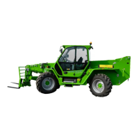
REAR HYDRAULIC OUTLET
To understand the operation of the rear hydraulic connection, refer to the following instructions:
- selector "S" on "0": the rear hydraulic connections are deactivated and the functions of the joystick (1) are those described
in chapter "COMMANDS AND INSTRUMENTS"
- selector "S" on "1": to control the rear hydraulic connection, turn the right wheel of the joystick (J) to "3A" or "4B" to use the
corresponding rear hydraulic connections
- selector "S" on "2": the oil is sent in a continuous manner to the hydraulic connection "3A" without using the joystick (J).
WARNING! The hydraulic system of the rear hydraulic outlet is not equipped with valves or seals able to
support lifted loads (for example a dumb body). For these kind of use verify that the attachment is equipped with
appropriate blocking system against accidental load descent.
Before operating with the rear hydraulic outlet, be sure to have disconnected both the hydraulic circuit of the
attachment locking system and the hydraulic line to the attachment fitted to the front carriage.
With work completed, disconnect the rear hydraulic outlets; if not, when using the attachment fitted to the front
carriage, the equipments linked to the rear hydraulic outlet would be activated.
The maximum working pressure of the rear hydraulic outlet is 210 bar.
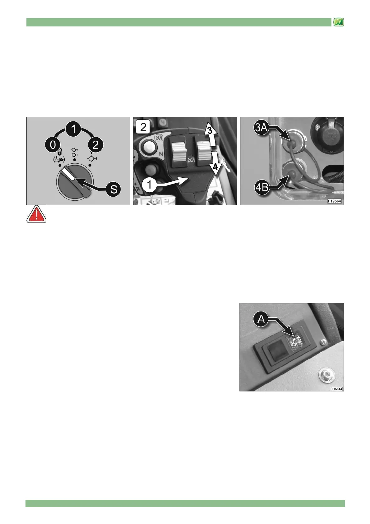
REAR WHEEL CENTRING INDICATOR ON THE MACHINE AXIS
Before carrying out a transfer on public roads, it is mandatory to align the wheels
of the rear bridge to the longitudinal axis of the machine by proceeding as
follows:
- select the four wheel coordinated steering or crab steering
- carry out the steering manoeuvre until the rear axle wheels are parallel to the
machine axis. the operator is notified that alignment is completed by indicator
"A" which lights up on control panel "P1".
Before carrying out a transfer on public roads, select steering on the front axis
(lever 29 in position "B").