7 - PERIODIC SAFETY INSPECTIONS
7 - 6
SOUND-VISUAL ALARMS AND MOVEMENT BLOCKING OF THE ANTI-OVERTURN SYSTEM
Your machine is fitted with two micro-switches (one on the right rear axle shaft and one on the left rear axle shaft) which control
the anti-overturn system. Inasmuch, carry out the safety check on both rear axle shafts, proceeding as follows:
WARNING! When carrying out the following operations, it will necessary to leave the driver's cab. Always
switch off the engine before leaving the driver's seat.
It is recommended to use a load with a weight of about 2/3 of the maximum load for the test.
1) Operate on solid, level ground
2) Fit the forks on the machine
3) Choose a load whose weight is known with a good approximation (± 10%)
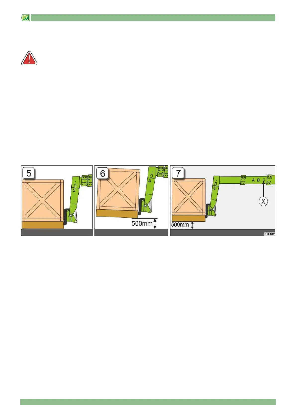
4) Pick up the load with the forks (Fig.5)
5) Make sure that the machine is level and centred in reference to the longitudinal axis; also check that the wheels are aligned
to the chassis frame
6) Lift the load to about 500 mm above ground (Fig.6)
7) Ascend with the right tyre on a step having a minimum height of 10 cm
8) Tilt the machine crossways and clockwise (see "CROSSWAYS TILT CONTROL LEVER" in section "COMMANDS AND
INSTRUMENTS") in order to bring the right hand rear semi-axle to the end of its travel
9) Extract the boom until the point where the anti-overturn system intervenes (sound and visual alarm, block of movements)
10) Check the length of the boom in reference to the "X" letter which is the closest to the fixed part of the boom
11) On the basis of the load used for the test, check if the "X" letter where the system has intervened matches the letter
foreseen by the machine's load chart found in the cabin. The tolerance for system intervention is ± 400 mm in relation to
what is indicated in the diagram (Fig. 7)
12) Completely retract the telescopic boom
13) Place the load on the ground
14) Drive off the step under the rear right wheel
15) Reset the crossways tilt corrector in the central position
16) Ascend with the left tyre on a step having a minimum height of 10 cm
17) Tilt the machine crossways and anticlockwise (see "CROSSWAYS TILT CONTROL LEVER" in section "COMMANDS AND
INSTRUMENTS") in order to bring the left hand rear semi-axle to the end of its travel
18) Carry out the test operations indicated in points (9) to (15)
The test is successfully passed only if - when carrying put the above mentioned operations - the anti-overturn system works
correctly on both sides of the rear axle. If even one of the two anti-overturn control systems does not work correctly, do not use
the machine and contact the Technical Assistance Service of Merlo S.p.A.