4 - COMMANDS AND INSTRUMENTS
4 - 17
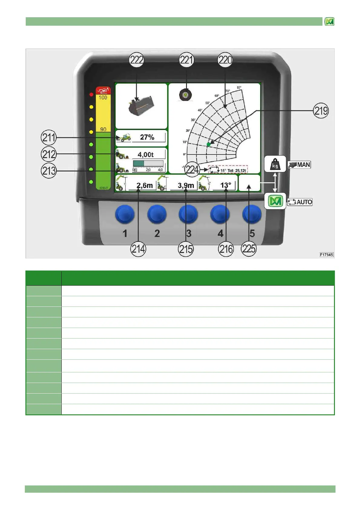
The main screen displays the following information:
REF. DESCRIPTION
211
Percentage longitudinal stability limit
212
Maximum liftable load, in the point where the telescopic boom is located, in relation to the attachment
213
Graphics bar indicating the load effectively lifted in relation to the attachment mounted
214
Height of load from ground (in metres)
215
Distance of load from external limit of tyres (or stabilisers, if present) (in metres)
216
Telescopic boom lifting angle (in degrees)
219
Colour indicator (green – yellow – red) of the position of the lifted load on the carriage
220
Machine load chart in relation to the attachment mounted (auto-identification) or the position of selector switch
(204) (manual identification)
221
Indication when operating the machine on tyres
222
Image of attachment mounted and auto-identified by the system
224
Weighing information: operating mode, lifting angle set, total weight
225
In MAN WEIGHING mode: Manual weighing – In AUTO WEIGHING mode: No command