4 - COMMANDS AND INSTRUMENTS
4 - 13
LOAD LIMITER FOR LIFTING ATTACHMENTS (43)
(valid for models P37.12PLUS - P38.12PLUS - P38.13PLUS - P38.14PLUS - P40.9PLUS - P40.17PLUS - P60.10 - P72.10)
Lifting attachments (fitted with a hook) having a lower maximum capacity than the
capacity of the machine are fitted with a load limiting system designed to protect
the attachment when performing lifts/hoists with the machine boom.
Below are listed several types of attachments fitted with a load limiter:
- fly jib with hook, fly jib with winch (max. capacity 600kg or 1500kg)
- winch on LIFT BOX platform
- lifting boom, telescopic lifting boom
- etc, etc…
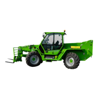
• PREPARING THE MACHINE FOR USE WITH THE LOAD LIMITER
- hook up the attachment to the machine platform
- connect any hydraulic hoses (Fig.1)
- connect the electrical connection from the attachment to socket "A" on the head
of the boom (Fig.2) (see paragraph "QUICK-COUPLING ATTACHMENTS" in
the "ATTACHMENTS" Section)
The machine is ready for operation.
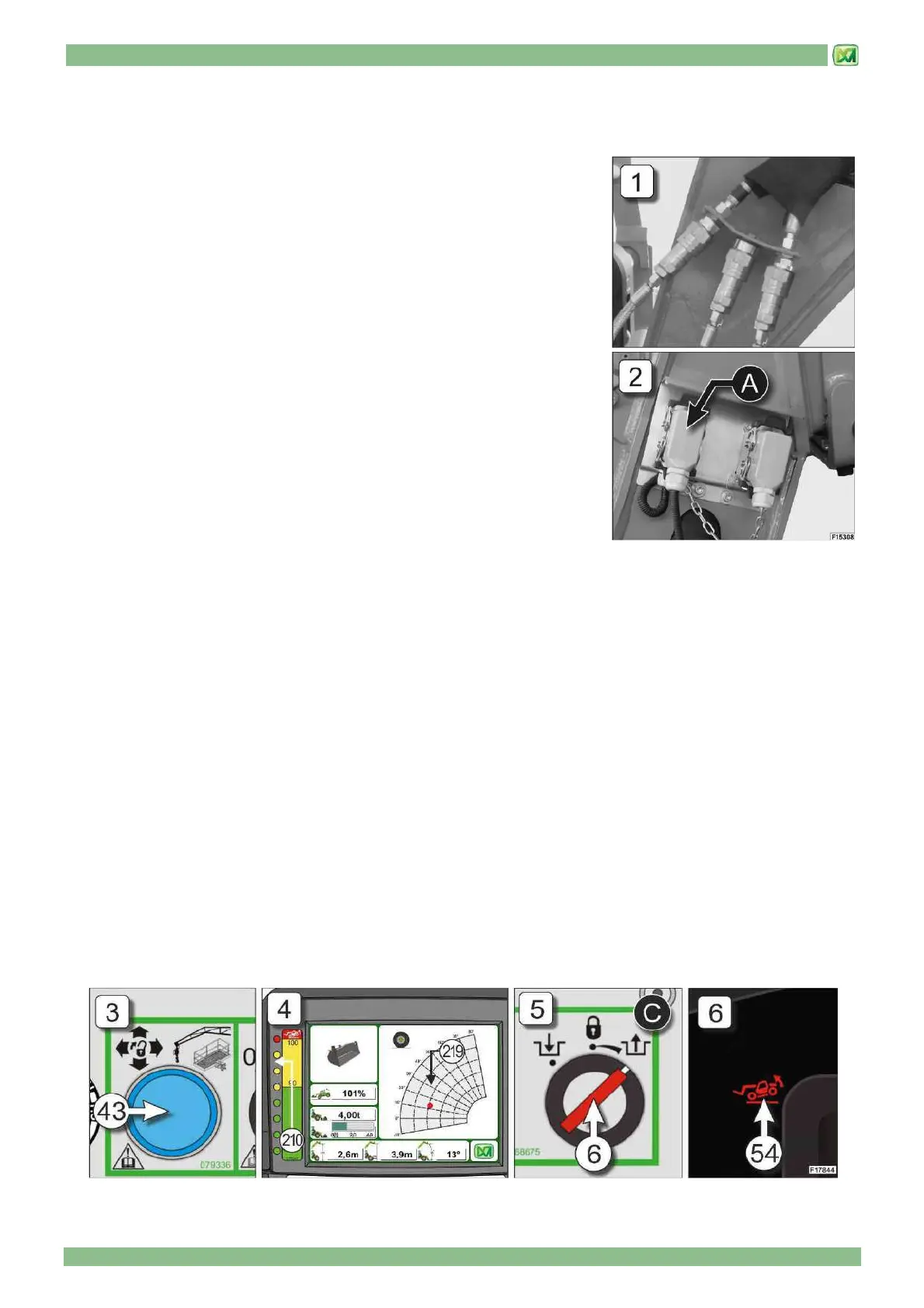
• ACTIVATING THE LOAD LIMITER
The load limiting device is set off when the load lifted exceeds the maximum load
capacity of the attachment. In this case, the system blocks all machine controls and
activates the following indicators:
- indicator light in button (43) on the control panel (Fig. 3)
- green-yellow-red indicators on the graphic LED bar (210) (Fig. 4)
- red indicator (219) of the dynamic load chart (Fig. 4)
In this case, the operator must perform the movements that do not worsen the overload on the attachment, as they are required
to restore safe working conditions (indicator light 43) OFF and green indicators (210-219 ).. To do so, proceed as follows:
- press and hold down the button (43)
- use the joystick (1) in the cab to perform movements that do not worsen the overload on the attachment, until safe working
conditions are restored
If, during these manoeuvres, the operator performs a movement that worsens the overload on the attachment, the system
blocks machine controls again, indicators (210 and 219) are red and after 5 seconds the indicator light in button (43) also
comes ON again. To reset controls and restore the machine to safe working conditions, repeat the operations described above.
The system envisages a maximum of 3 attempts to reset safe operating conditions. If, after the third attempt, an overload
situation affecting the attachment occurs again, the system will block the machine controls and activate:
- Indicator light (54) on instrument panel (C) (Fig.5)
- green-yellow-red indicators on the graphic LED bar (210) (Fig. 4)
- red indicator (219) of the dynamic load chart (Fig. 4)
In this condition, turn the operating mode selector switch key (6) to position "C" (emergency movements), then slowly and
carefully make the necessary movements to make the load transportable (for further information, refer to the "WORKING
MODE SELECTOR" and "FRONT OVERTURN PREVENTION CONTROL" paragraphs in the "CONTROLS AND
INSTRUMENTS"). (Fig.6)