4 - COMMANDS AND INSTRUMENTS
4 - 22
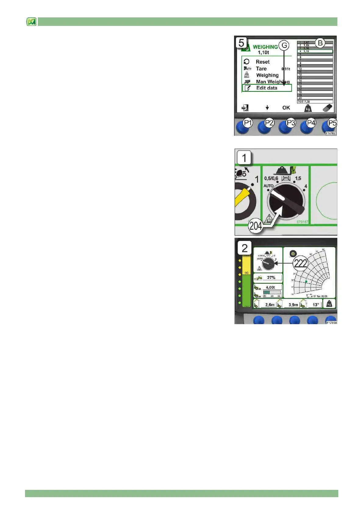
6) MODIFYING WEIGHTS (G)
If one or more weights stored in Table "B" have to be modified or cancelled, this
can be done using the modification function on the WEIGHING SCREEN. To do
this, move around the weighing screen using button (P2) and select the item
"EDIT DATA"; then press button (P3) to confirm. At this stage, the manual
weighing and eraser symbols respectively under buttons (P4) and (P5).
To select the weighing to be modified, press button (P2) until the desired
weighing operation is highlighted (flashing) and then press button (P4) to repeat
a manual weighing or button (P5) to cancel the weighing. (Fig.5). Press the
button (P3) to confirm the selection.
Press button (P1) to return to the main screen
• SELECTOR SWITCH FOR TYPE OF ATTACHMENT MOUNTED ON THE
CARRIAGE
The machine is fitted with a selector switch (204) with 4 stable positions allowing
the operator to set (manually or automatically) the type of attachment mounted
on the carriage in order to define the appropriate capacity chart for the machine
+ attachment set-up.
The 4 positions of the selector switch (204) for the type of attachment installed
on the carriage are (Fig.1):
a) AUTO: auto-identification of the attachment installed
b) 0.5/0.6: attachments with a centre of gravity of the lifted load at 0.5 / 0.6
metres from the carriage
c) 1.5: attachments with a centre of gravity of the lifted load at 1.5 metres from
the carriage
d) 4: attachments with a centre of gravity of the lifted load at 4 metres from the
carriage
A graphic depiction of the selector switch (204) is also provided on the display
(D) in the cab in field (222) (Fig.2) and is displayed when:
- there is no attachment mounted on the carriage.
- the attachment mounted on the carriage is not identified.
- there is a fault or problem with the auto-identification system for an attachment
mounted on the carriage
When an attachment is installed and identified on the carriage and the system is
functioning correctly, the graphic depiction of the selector switch (204) in field
(220) shows the symbol of the attachment installed (see below in this paragraph)
For a better understanding of the functional modes of the selector switch (204), refer to the following instructions: