Chapter 12 Serial Bus Trigger and Decode (Optional)
119
Note: When there is parity bit, the data word length indicates the total length of data bit plus parity
bit. When there is no parity bit, the data word length is considered to be the length of data bit. For
example, if the data word length is 8bit, when there is no parity bit, it means that the total length of
data bits is 8bit; when there is parity bit, it means that the total length of data bits is 7bit, and there is
parity bit of 1 bit.
⚫ Trigger mode
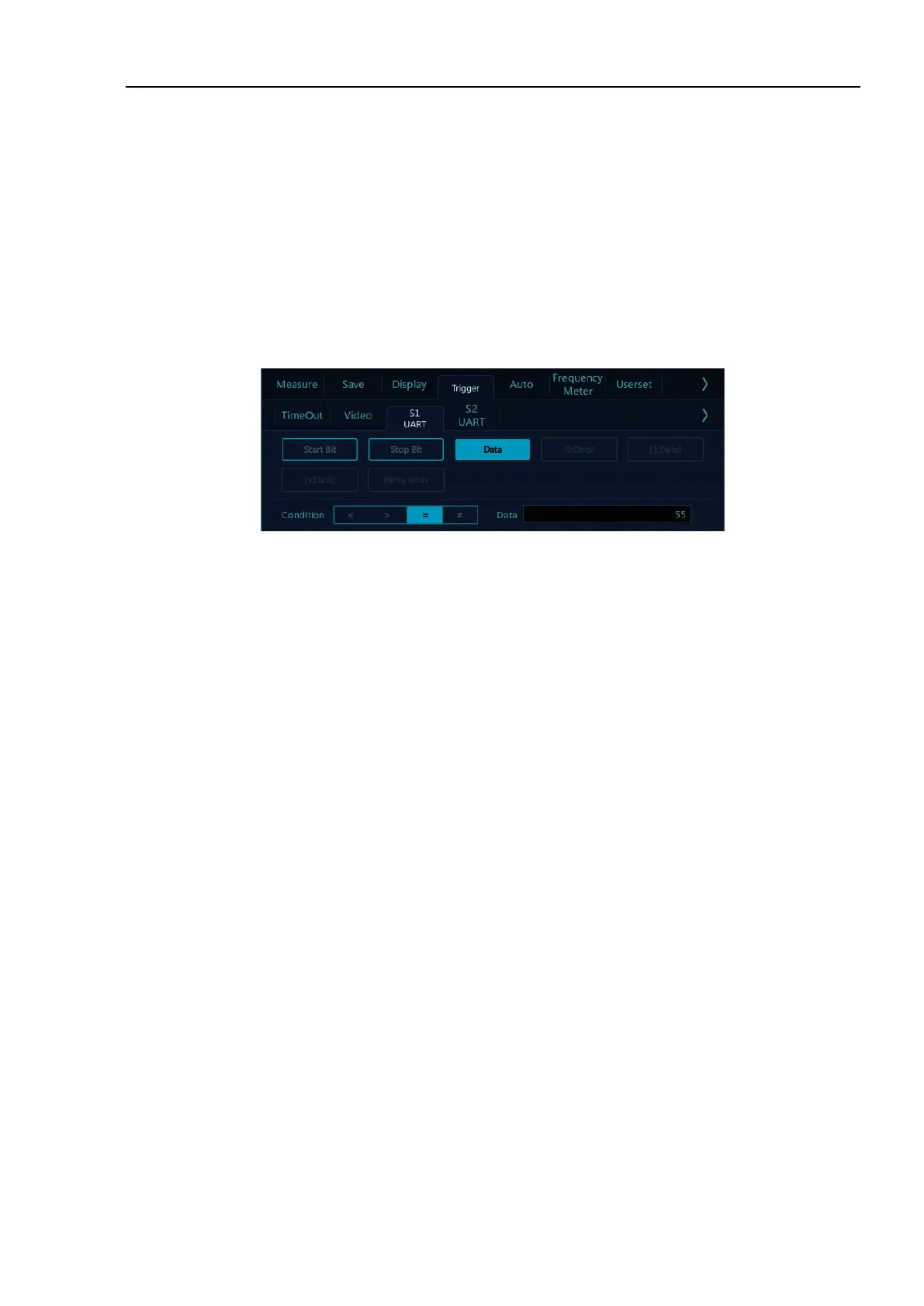
Open the trigger configuration menu and select the appropriate trigger type; when choosing UART bus
trigger, the trigger type, trigger relationship and trigger data need to be set, as shown in Figure 12-6:
Figure 12-6 Trigger Setting Menu
After selecting the trigger data, use the pop-up virtual keyboard to modify it, enter the value, and click
“Enter” on the virtual soft keyboard to complete the setting.
UART trigger configuration menu description:
a) Start bit — trigger at the start bit of the measured signal;
b) Stop bit — trigger at the stop bit of the measured signal, no matter the measured signal uses 1, 1.5, or
2 stop bits or not, the trigger will occur at the first stop bit.
c) [data] — Trigger at the specified data bit, when measured signal data bits are effective as 5 to 8bits,
select [data], and select the trigger relationship as” =“ “ >“ “ <“ “≠”, then select “Trigger Data”, press
data on the touch screen, and use the pop-up virtual keyboard to modify;
d) [0:data] — the measured signal data bits is 9bits (the 9th bit is parity bit). Only when the 9th bit is 0,
then trigger. The trigger relationship, trigger data configuration are the same as those of [data] trigger;
e) [1:data] — the measured signal data bits is 9bits (the 9th bit is parity bit). Only when the 9th bit is 1,
then trigger. The trigger relationship, trigger data configuration are the same as those of [data] trigger;
f) [x:data] — the measured signal data bits is 9bits (the 9th bit is parity bit). No matter what the value
of the 9th bit is, trigger at the designated data bit. The trigger relationship, trigger data configuration
are the same as those of [data] trigger;
g) Parity Error — valid when there is parity check at parity bit, trigger while parity error.
 Loading...