Chapter 13 Remote Control
145
the entered IP address.
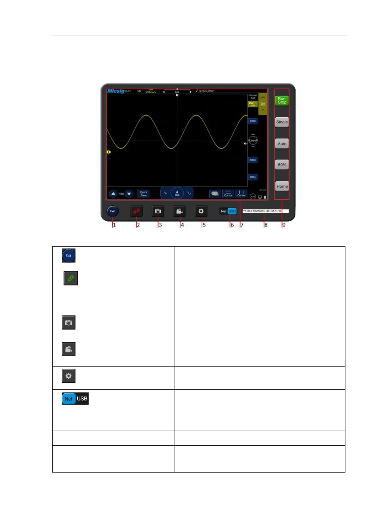
13.1.3 Main Interface Introduction
Figure 13-2 Host Computer Interface
1. Host computer on/off button
Click to exit the host computer software
2 Oscilloscope connection status
button
The button has two states:
Green: Connect to selected oscilloscope when clicked
Red: Disconnect from oscilloscope when clicked
Click to take photo quickly. Pictures are stored in the local
directory C:\Users\Public\Pictures
Click to open or close video record function. Videos are stored
in local directory C:\Users\Public\Videos
5. Host computer storage button
Set photo taking and video recording storage locations
6. Select oscilloscope connection
mode
USB and WIFI connections are available
Note: WIFI connection must ensure that oscilloscope and computer
are in the same network
7. Host computer display area
Synchronous display with oscilloscope
8. Oscilloscope information display
Display oscilloscope model, connection mode, SN, IP and
other information, select the oscilloscope to be connected