Chapter 5 Trigger System
51
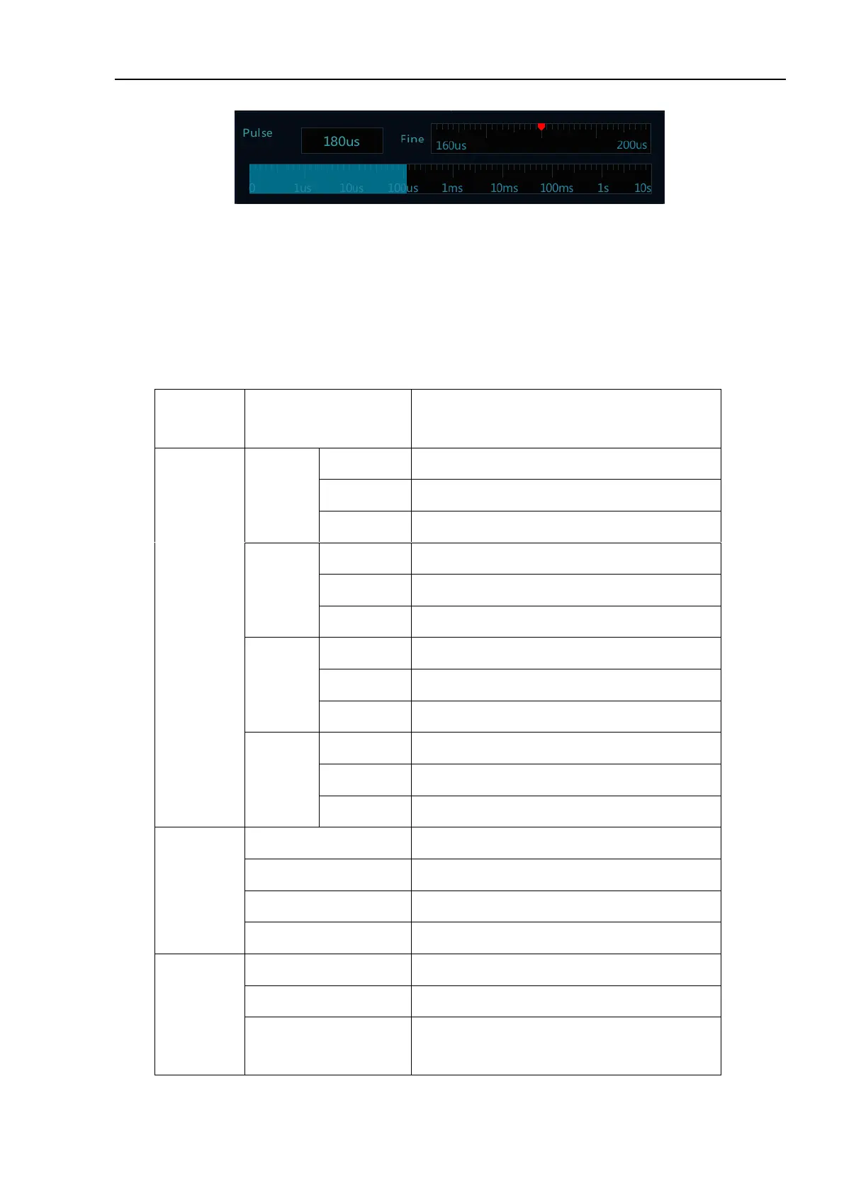
Figure 5-19 Pulse Width Time Adjustment Interface
5.4 Logic Trigger
Trigger happens when the level between analog channels satisfies a certain logical operation (AND, OR, NAND,
NOR) and the signal voltage reaches the set trigger level and the trigger logic width (8ns~10s). Logic trigger
menu descriptions are shown in the table below:
Select the logic of trigger source as “AND”
Select the logic of trigger source as “OR”
Select the logic of trigger source as “NAND”
Select the logic of trigger source as “NOR”
Trigger when the logic changes to true value
Trigger when the logic changes to false value
If logic status for hold time as <, >, =, ≠T, then
trigger