68
Note:
If the waveform required for measurement is not fully displayed on the screen, “Forward Clipping” or “Negative Clipping”
is displayed at the position of the measured value.
When the math function is operated, if source channel waveform is fully displayed, and the math waveform appears to be
off the screen, the measured value of math waveform will not be influenced.
If source channel is clipped, the measured value of math waveform is the source channel value during screen wave clipping.
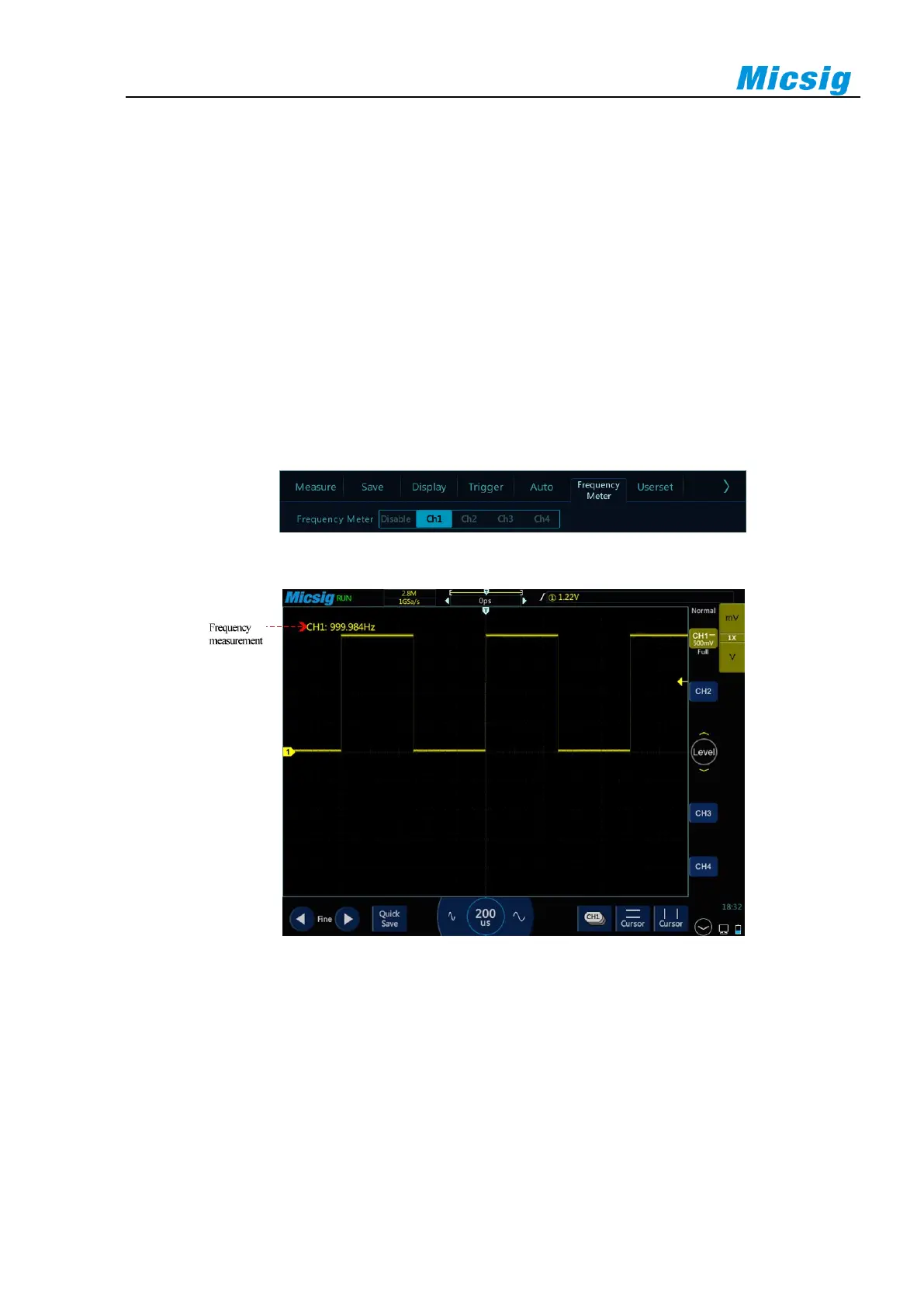
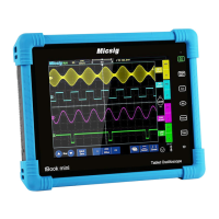
6.2 Frequency Meter Measurement
Open the main menu, tap “Frequency Meter” to enter the hardware frequency meter setting menu, and select the
channel to be measured, as shown in Figure 6-5. The measured value is displayed in the upper left corner of the
screen, as shown in Figure 6-6.
Figure 6-5 Frequency Meter Measurement Menu Open
Figure 6-6 Frequency Meter Measurement
6.3 Cursor
Open cursor and place it on the measurement point to read the waveform measurement value. There are two types
of cursors: horizontal cursor and vertical cursor. The horizontal cursor measures the vertical direction magnitude,
and the vertical cursor measures the horizontal direction magnitude, as shown in Figure 6-7.