Chapter 12 Serial Bus Trigger and Decode (Optional)
139
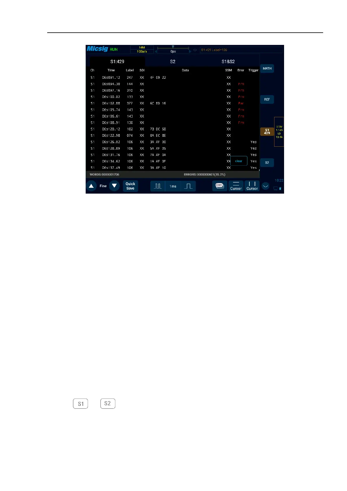
Figure 12-29 ARINC429 Text Interface
ARINC429 text interface description, as shown in Figure 12-29:
(1) “Ch”: bus channel.
(2) “Time”: intervals between the last read/write operations to current read/write operations
(3) “LABLE”: label, information identifier, displayed in octal.
(4) “SDI”: source/target identifier, displayed in binary (displays XX if not identified separately).
(5) “Data”: content of the transmitted information, displayed in the selected numeration system.
(6) “SSM”: symbol/status matrix, displayed in binary (displays XX if not identified separately).
(7) “Error”: displays the frame error type (parity error Par, frame error Frm).
(8) “Trigger”: “Yes” means reach trigger condition.
12.7 1553B Bus Trigger and Decode
For correctly decoding 1553B bus data and making trigger stable, the bus configuration, trigger mode set and
trigger level need to be adjusted.
⚫ Bus configuration
Tap or to open the bus configuration menu, the data source and display hexadecimal need
to be set, as shown in Figure 12-30: