Chapter 2. Quick Start Guide of Oscilloscope
11
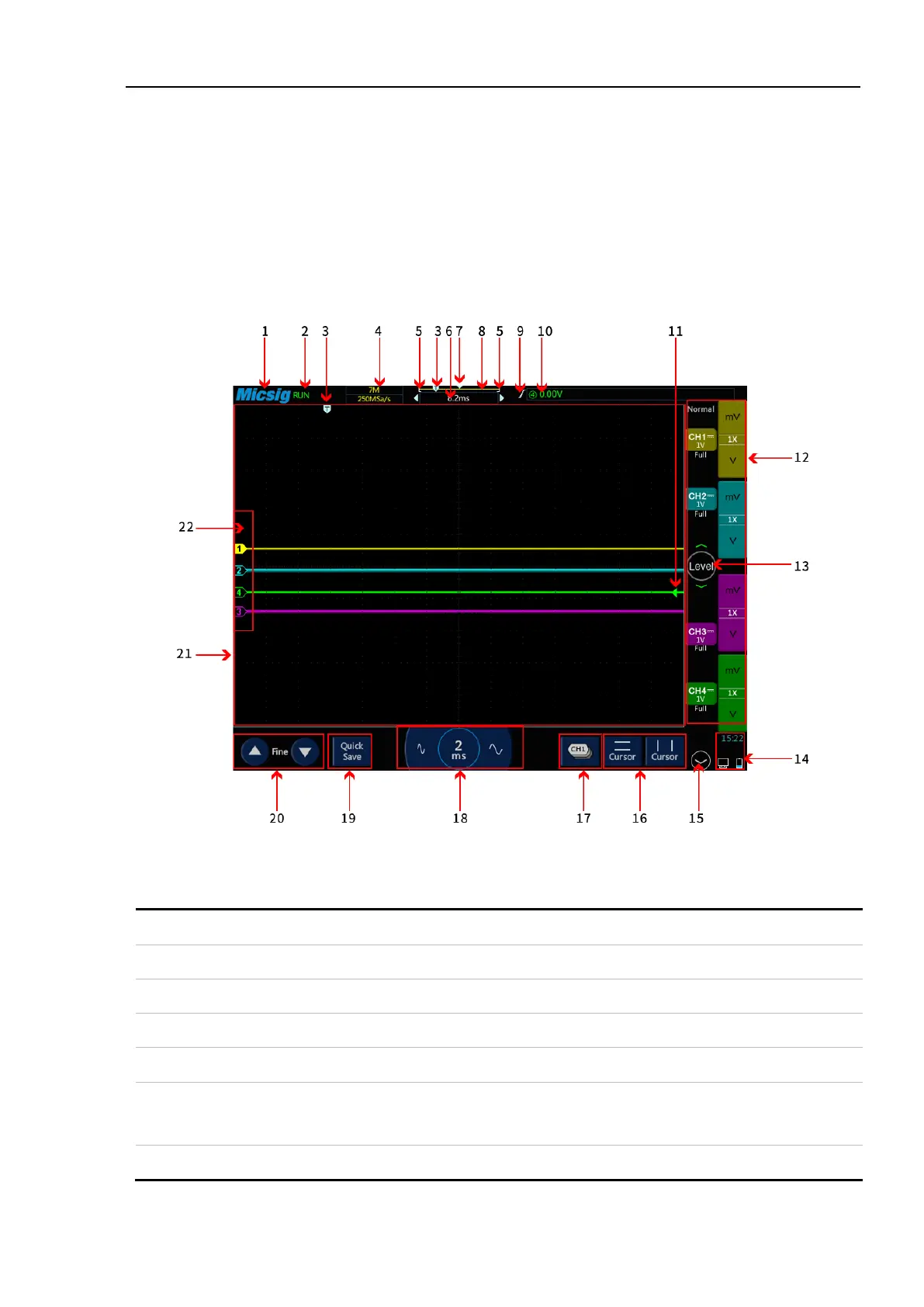
2.6 Understand the Oscilloscope Display Interface
This section provides a brief introduction and description of the tBook mini Series oscilloscope user’s interface.
After reading this section, you can be familiar with the oscilloscope display interface content within the shortest
possible time. The specific settings and adjustments will be detailed in subsequent chapters and sections. The
following items may appear on the screen at a given time but not all items are visible. The oscilloscope interface
is shown in Figure 2-4.
Figure 2-4 Oscilloscope Interface Display
Oscilloscope status, including RUN, STOP, WAIT, AUTO