Chapter 4 Vertical System
33
4.4 Open Channel Menu
Tap the channel icon (channel is open) to open the channel menu.
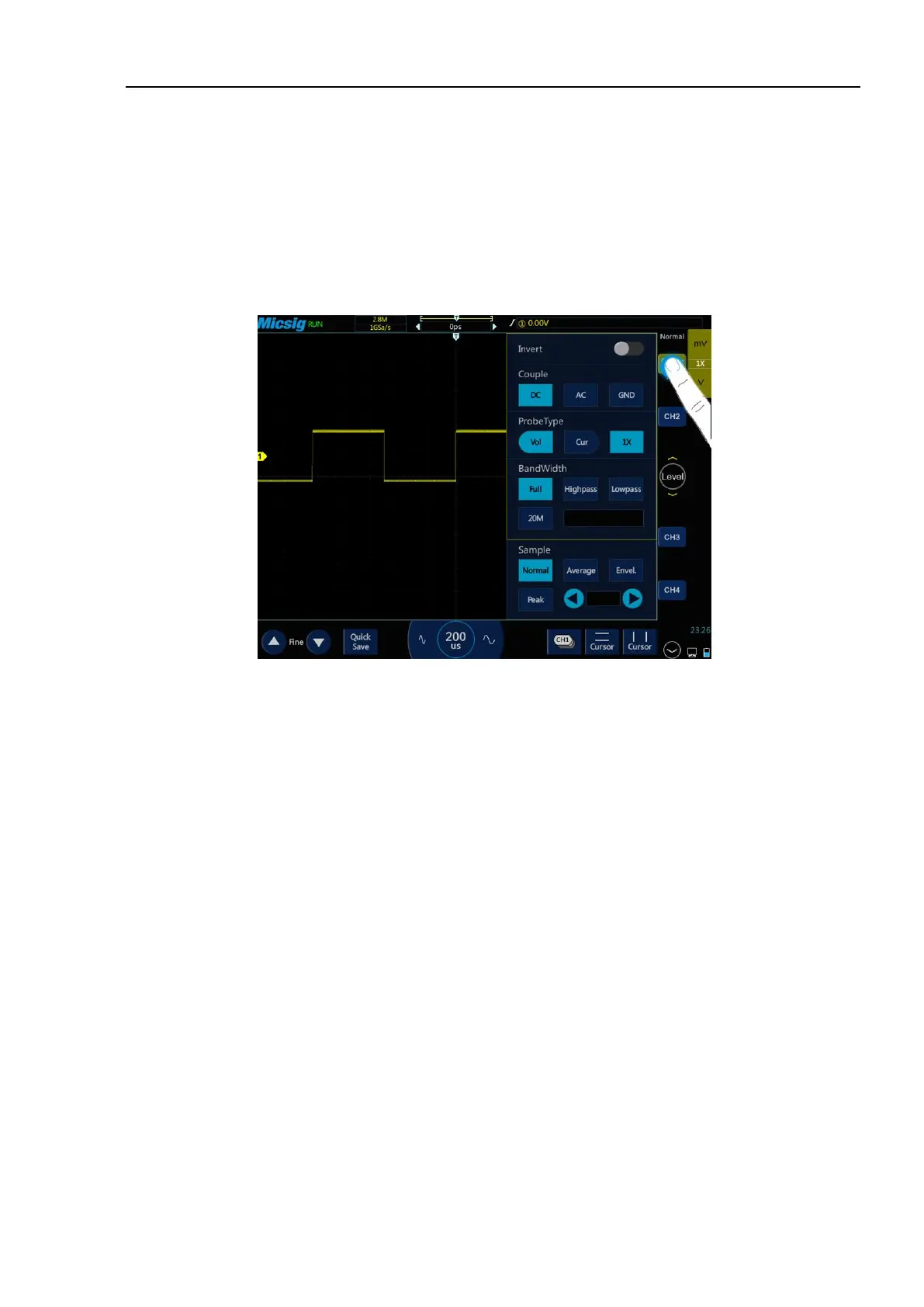
The channel menu is shown in Figure 4-7. Channel waveform inversion, channel bandwidth limit, probe type,
probe attenuation factor, channel coupling mode, and sampling mode can be set in the vertical menu.
Figure 4-7 Channel Switching Icon and Menu
4.4.1 Set Channel Coupling
Tap the icon under “Coupling Mode” and select “DC”, “AC” and “GND” channel coupling modes in the pop-up
box.
DC: DC coupling. Both the DC component and the AC component of the measured signal can pass, and can be
used to view waveforms as low as 0 Hz without large DC offset.
AC: AC coupling. Measured DC signal is blocked, and only the AC component can be allowed to pass, and used
to view waveforms with large DC offsets.
GND: Internal input ground, disconnecting from external input.
The oscilloscope is connected to the square wave signal with a frequency of 1KHz, an amplitude of 2V and an
offset of 1V. The waveforms of the channel couplings of DC, AC, and GND are shown in Figures 4-8, 4-9, and
4-10.