Chapter 12 Serial Bus Trigger and Decode (Optional)
121
(6) Decode data and the corresponding waveform area
(7) Signal source Ch1
UART decode data packet description:
(1) Decode data packet displays real-time data about the bus activities;
(2) Decode data displays as hexadecimal system in white;
(3) When the word length is 5-8 bits, the decode data displays as two bits of hexadecimal; when the word
length is 9 bits, the decode data displays as 3 bits of hexadecimal, and the 9th bit displays at the left
side;
(4) When there is error in decode data, if the error is at stop bit, the data displays in yellow, if it is parity
error, data displays in red;
(5) When “?” appears, the time base needs to be adjusted to view decode results.
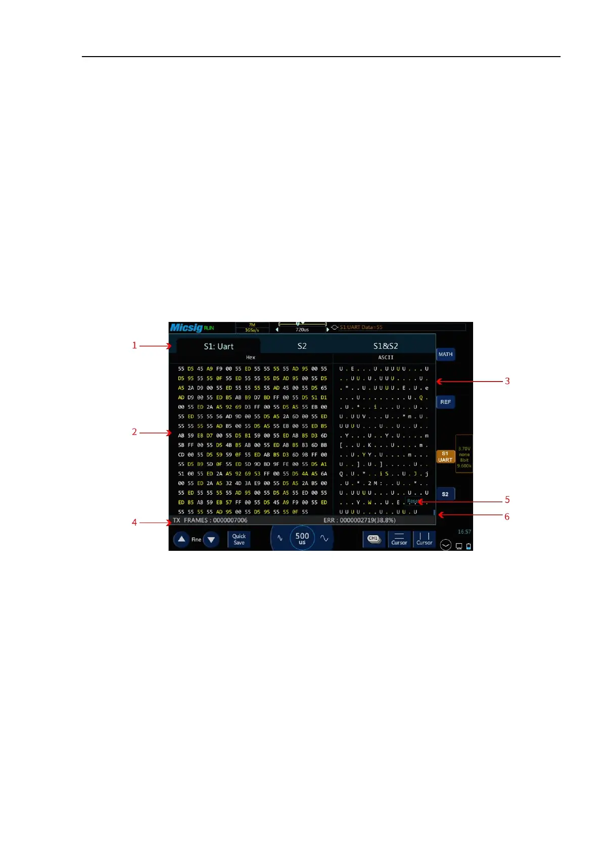
Figure 12-8 UART Text Interface
UART text interface description, see Figure12-9:
(1) S1/S2/S1&S2 is channel configuration bus information.
(2) Area for decode data.
(3) ASCII code corresponding to the text data (when the data format is 9 bits and there is no parity bit,
ASCII code corresponds to lower 8 bits of data on the left side).
(4) Counter: Calculates the total number of frames and the percentage of ERR (parity error and stop bit
error) frames.
(5) Clear: Clear the counter data.
 Loading...