130
Tap or to open the bus configuration menu, the following need to be set:
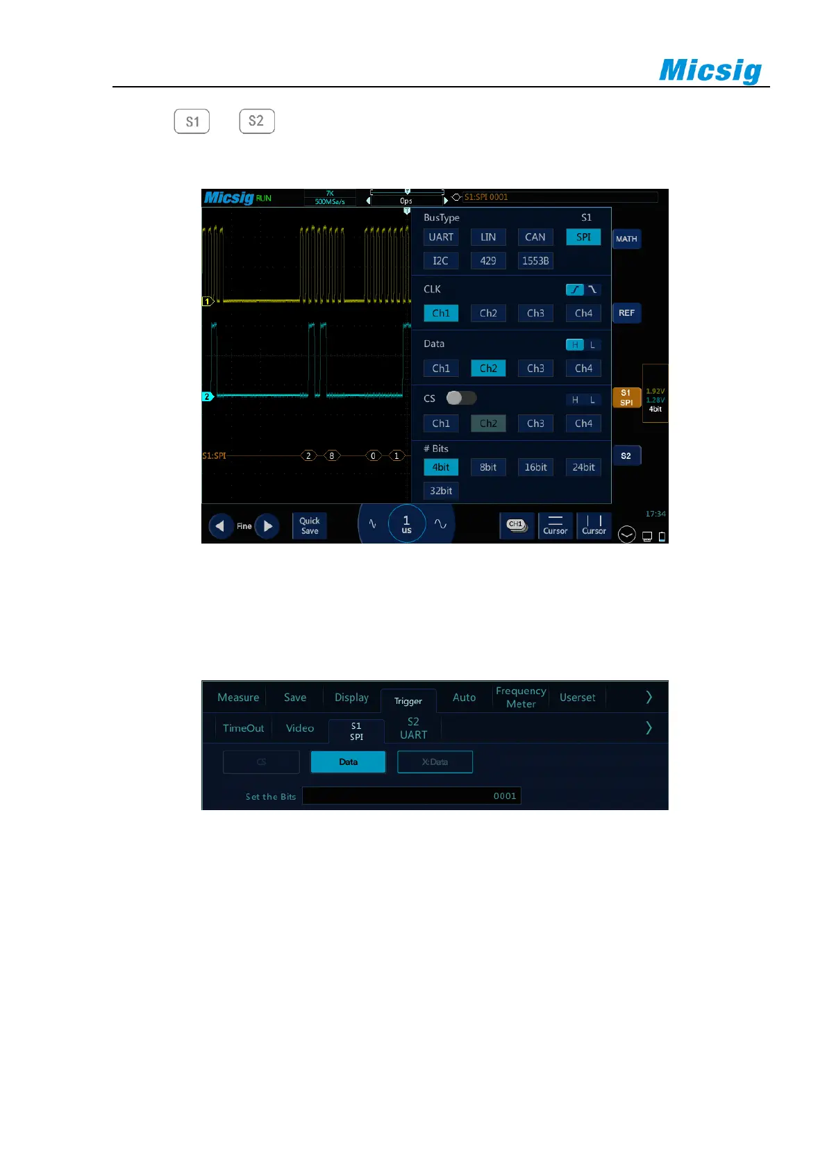
Clock source, data source, chip select signal, and data bits, as shown in Figure 12-18:
Figure 12-18 SPI Bus Configuration Menu
⚫ Trigger mode
Open the trigger configuration menu and select the appropriate trigger type; when selecting the SPI bus
trigger, as shown in Figure 12-19:
Figure 12-19 SPI Trigger Mode Configuration Menu
The operation method is the same as CAN frame ID to be matched in the configuration, and will not be
repeated here.
Note: According to the data byte length set by bus decode, the value of the relevant bit within the byte
length is set. Trigger when the corresponding bit on data bus matches the set value.
⚫ SPI serial bus
The measured signal channel Ch1 is connected to CLK, Ch2 channel is connected to DATA, the bus idle
state is high, the clock rising edge is sampled; the data word length is 4 bits; the CS chip select is off; the
 Loading...