Chapter 12 Serial Bus Trigger and Decode (Optional)
135
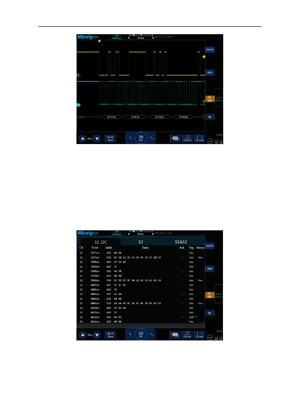
Figure 12-24 I2C Graphic Interface
I2C decode data packet description:
(1) Decode data packet displays real-time data about the bus activities.
(2) Decode data displays as hexadecimal system.
(3) Address content display: Read address displays in green, write address displays in yellow, and data
displays in white. “W” denotes write operation, “R” denotes read operation, “D” denotes decode data,
and “~A” denotes no Ack bit.
(4) When “?” appears, the time base needs to be adjusted to view decode results.
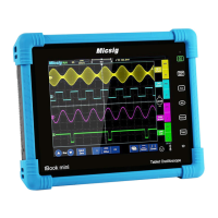
Figure 12-25 I2C Text Interface