Chapter 12 Serial Bus Trigger and Decode (Optional)
137
⚫ Trigger mode
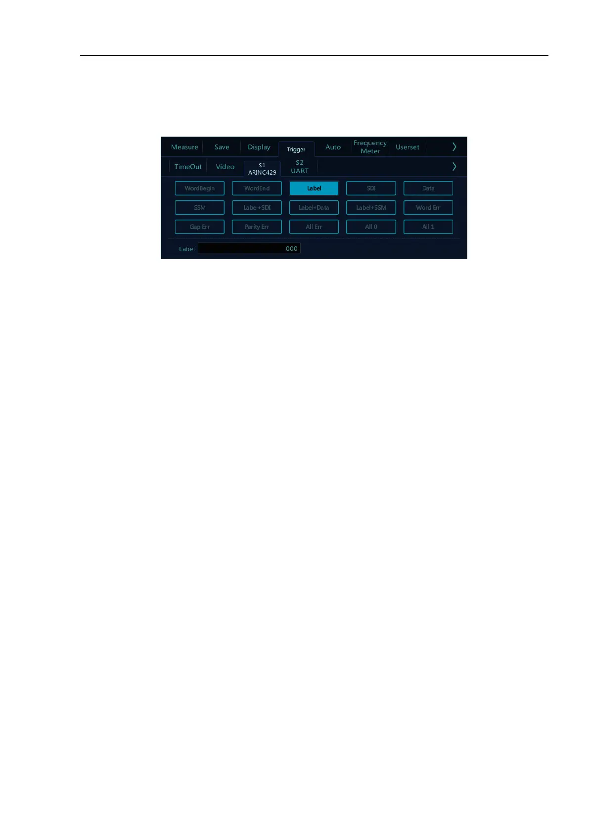
Open the trigger configuration menu and select the appropriate trigger type; when the ARINC429 bus trigger
is selected, click the trigger type and relationship on the screen, as shown in Figure 12-27:
Figure 12-27 ARINC429 Trigger Mode Configuration Menu
If LABEL, SDI (source identifier), DATA or SSM (symbol/status mark) trigger are used, after selecting
trigger mode, use the pop-up virtual keyboard to modify it, enter the value, and click “Enter” on the virtual
soft keyboard to complete the setting.
Trigger configuration menu description:
a) WordBegin: Trigger at the word start.
b) WordEnd: Trigger at the word stop.
c) Label: Label, triggered when the specified tag value occurs.
d) SDI: Source identifier, triggered on the specified source terminal.
e) Data: Trigger on the specified data.
f) SSM: Symbol/status mark, triggered on the specified symbol status matrix.
g) Label+SDI: Trigger on the specified label and the specified source terminal.
h) Label+Data: Trigger on the specified label and the specified data.
i) LABEL+SSM: Trigger on the specified label and the specified symbol status matrix.
j) Word Err - Triggered when a word error occurs.
k) Gap Err: Triggered when a gap error occurs.
l) Parity error: Triggered when a verification error occurs.
m) All Err: Triggered when any of the above errors occur.
n) All 0: Triggered when any bit with the value of zero occurs.
o) All 1 -: Triggered when any bit with the value of 1 appears.
⚫ ARINC 429 serial decode
The measured signal source is CH1, the decode format is LABEL+DATA, the display is in hexadecimal, the