18
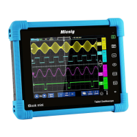
Figure 2-13 Probe Connection
3) Open the channel (if the channel is closed).
4) Adjust the oscilloscope channel attenuation coefficient to match the probe attenuation ratio.
5) Tap button or manually adjust the waveform vertical sensitivity and horizontal time base.
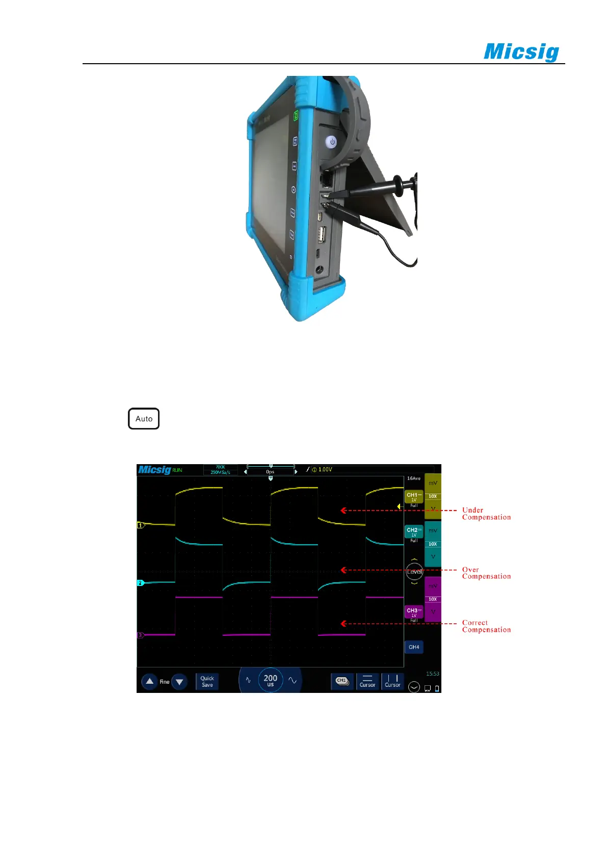
Observe the shape of the waveform, see Figure 2-14.
Figure 2-14 Probe Compensation
If the waveform on the screen is shown as “under-compensation” or “over-compensation”, please adjust the
trimmer capacitor until the waveform shown on the screen as “correct-compensation”. The probe adjustment is
shown in Figure 2-15.
 Loading...