Chapter 5 Trigger System
49
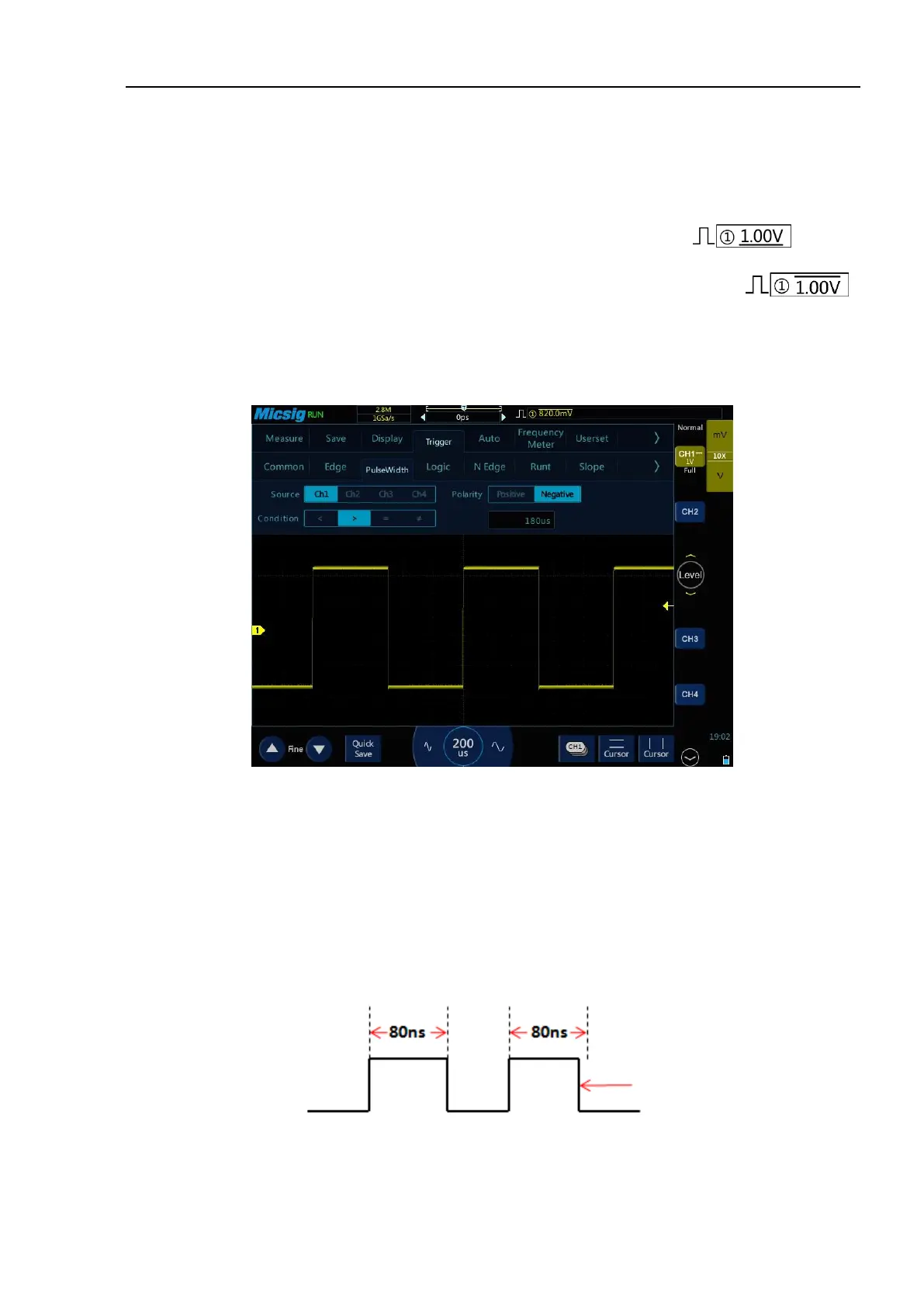
Pulse width trigger setting description:
1) Pulse polarity selection
The selected pulse polarity icon is displayed in the upper right corner of the display screen. The positive
pulse is higher than current trigger level (CH1 positive pulse indication icon ), and the
negative pulse is lower than current trigger level (CH1 negative pulse indication icon ).
When triggered on positive polarity pulse, if the restrictions are true, the trigger will happen on the high-to-
low transition of the pulse; when triggered on negative polarity pulse, if the restrictions are true, the trigger
will happen on the low-to-high transition. (Figure 5-14 Negative Pulse Level Flip)
Figure 5-14 Negative Polarity Pulse Level Flip
2) Trigger condition and pulse width time setting
Time restrictions that can set in the trigger condition: <, >, =, ≠.
⚫ Smaller than the time value (<)
For example, for positive pulse, if it is set as T<80ns, the trigger will happen stably only when the pulse
width is smaller than 80ns (Figure 5-15 Trigger Time T<80ns).
Figure 5-15 Trigger Time T<80ns