84
Note: Signals with DC components or deviations can cause errors or deviations in the FFT waveform components. AC
coupling can be selected to reduce DC components.
Spectrum type
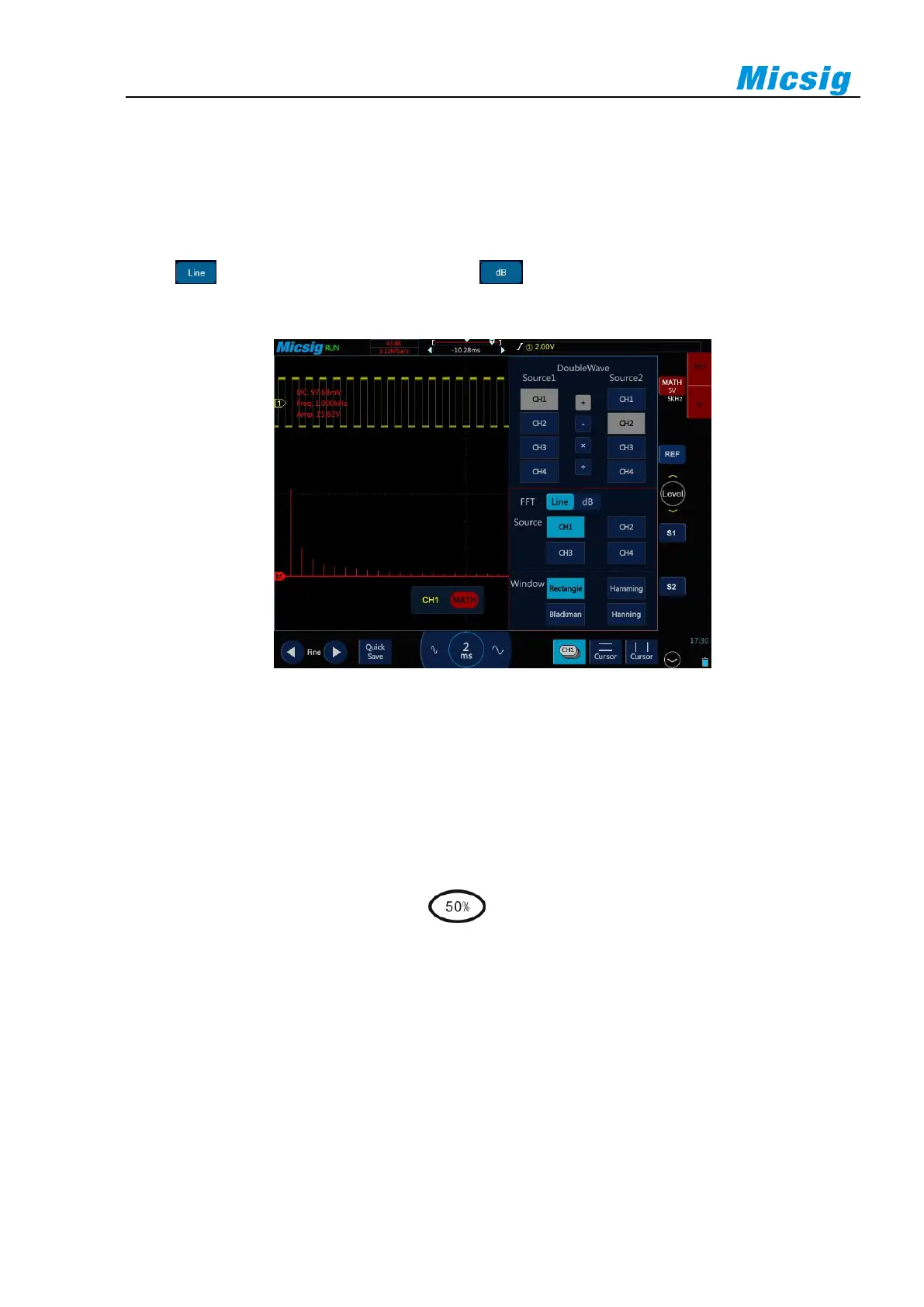
Select , the vertical axis reads V or A; select , the vertical axis reads dB. When the spectrum is
linear, the waveform is shown in Figure 8-4.
Figure 8-4 Spectrum Amplitude as V-Hz
Adjust FFT waveforms
Waveform position
⚫ Select math channel as the current channel. After touching math waveform on the screen with one
finger, adjust the waveform display position by dragging upward and downward, leftward and
rightward, or tap the fine adjustment button in the lower left corner of the screen for fine adjustment
⚫ Move the channel horizontally, tap , tap the "time base" item, and move the leftmost (0Hz)
of the waveform to the horizontal center of the screen.
Horizontal time base scale
Select math channel as the current channel, tap the time base adjustment button, and adjust the horizontal time
base scale. The horizontal time base is stepped in 1-2-5, and the waveform changes either.
For FFT measurement, the reading of the horizontal axis changes from time to frequency (Hz), and it no longer
shares the same time base with other analog channels. Therefore, before adjusting the horizontal frequency scale,
the math channel must be set as the current channel.