Technical Information
5
CVA 265x & CVA 266x
List of Figures
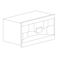
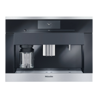
Figure D-1: CVA 2650/2660 Appliance Overview (Front) ................................................. 9
Figure D-2: CVA 2650/2660 Appliance Overview (Front Door Open) ............................. 10
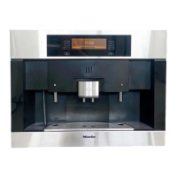
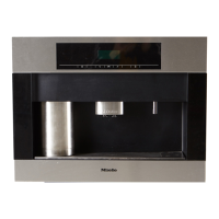
Figure D-3: CVA 2652/2662 Appliance Overview (Front) ............................................... 10
Figure D-4: CVA 2652/2662 Appliance Overview (Front Door Open) ............................. 11
Figure D-5: Component Overview (CVA 2650/2660) ...................................................... 12
Figure D-6: Component Overview (CVA 2652/2662) ...................................................... 13
Figure 010-1: Drip Tray Contact Springs ........................................................................ 16
Figure 010-2: Drip Tray Contacts .................................................................................... 16
Figure 010-3: Appliance Retaining Screws ..................................................................... 18
Figure 010-4: Door Switch .............................................................................................. 19
Figure 010-5: Water Tank Level Switch Removal ........................................................... 20
Figure 010-6: Top Casing Retaining Screws .................................................................. 21
Figure 010-7: Top Casing in the Service Position ........................................................... 21
Figure 010-8: Top Casing Removal ................................................................................ 22
Figure 010-9: Front Casing Retaining Screws ................................................................ 23
Figure 010-10: Valve Housing Seal Removal ................................................................. 24
Figure 020-1: Optical Interface Location ......................................................................... 26
Figure 020-2: Coffee Dispensing Nozzle Removal ......................................................... 31
Figure 020-3: Display Electronic Cover Removal (CVA 2650/2660 Shown) ................... 31
Figure 020-4: Display Electronic Removal, CVA 2650/2660 ........................................... 32
Figure 020-5: Display Electronic Removal, CVA 2652/2662 ........................................... 32
Figure 020-6: Door Retaining Screws ............................................................................. 33
Figure 020-7: Hinge Retaining Screws ........................................................................... 33
Figure 020-8: Removing the Serving-Area LEDs (CVA 2650/2660 shown) .................... 34
Figure 030-1: Water Path – Overview of Components ................................................... 37
Figure 030-2: Carrier Panel Retaining Screws ................................................................ 39
Figure 030-3: Hose Connections .................................................................................... 40
Figure 030-4: Component Locations on Carrier Panel .................................................... 41
Figure 040-1: Steam Valve Positions .............................................................................. 46
Figure 040-2: Cappuccinatore Components ................................................................... 48
Figure 050-1: Brewing Procedure ................................................................................... 51
Figure 050-2: Releasing the Capsule Magazine Drawer ................................................ 52
Figure 050-3: Brew Unit and Retaining Screws .............................................................. 53
Figure 050-4: Brew Unit Motor Assembly ....................................................................... 54
Figure 050-5: Ceramic Valve .......................................................................................... 54
Figure 050-6: Steam Valve Assembly ............................................................................. 55
Figure 050-7: Capsule Magazine Motor Assembly ......................................................... 56
Figure 050-8: Capsule Transport Motor Assembly ......................................................... 57
Figure 050-9: Capsule Transport Motor Assembly Components .................................... 57
Figure 050-10: Intermediate Plate Assembly .................................................................. 58
Figure 050-11: Capsule Magazine Optical Sensor ......................................................... 59
Figure 060-1: EPL 85x Connectors and Pin Locations ................................................... 61
Figure 060-2: Ceramic Valve Hose Connections ............................................................ 66
Figure 060-3: Capsule Transport Assembly .................................................................... 68
Figure 060-4: Modified Capsule Transport Arm with 55° Bezel (2650/2660) .................. 69
Figure 060-5: Grease ...................................................................................................... 70
Figure 060-6: Base Plate Removal ................................................................................. 75
Figure 060-7: Contact Springs in Housing ...................................................................... 75